Toyota Camry (XV70): Installation
INSTALLATION
PROCEDURE
1. INSTALL TAIL EXHAUST PIPE BAFFLE SUB-ASSEMBLY
HINT:
- Perform this procedure only when replacement of the tail exhaust pipe baffle sub-assembly is necessary.
- If the tail exhaust pipe baffle sub-assembly is removed, replace it with a new one.
(a) Type A (w/ Tail Exhaust Pipe Baffle)
| (1) Align the cutout of a new tail exhaust pipe baffle sub-assembly with the protrusion (for position alignment) of the tail exhaust pipe assembly as shown in the illustration. |
|
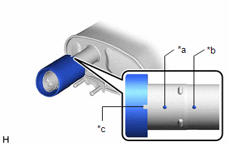
(2) Insert the tail exhaust pipe baffle sub-assembly to the position where it can be pressed in by hand.
| (3) Using a plastic-faced hammer and wooden block, uniformly tap the tail exhaust pipe baffle sub-assembly onto the tail exhaust pipe assembly. NOTICE:
|
|
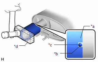
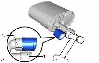
| (b) Type B (1) Align the cutout of a new tail exhaust pipe baffle sub-assembly with the guide line of the tail exhaust pipe assembly as shown in the illustration. (2) Using a plastic hammer, uniformly tap the tail exhaust pipe baffle sub-assembly onto the tail exhaust pipe assembly. |
|
2. INSTALL HEATED OXYGEN SENSOR (for Bank 1)
Click here
.gif)
3. INSTALL HEATED OXYGEN SENSOR (for Bank 2)
Click here
4. INSTALL FRONT EXHAUST PIPE ASSEMBLY (TWC: Rear Catalyst)
(a) Install 2 new gaskets to the front exhaust pipe assembly (TWC: Rear Catalyst).
(b) Connect the front exhaust pipe assembly (TWC: Rear Catalyst) to the exhaust pipe support.
(c) Install the front exhaust pipe assembly (TWC: Rear Catalyst) to the exhaust manifold (TWC: Front Catalyst) with 2 new bolts and 2 new nuts.
Torque:
43 N·m {438 kgf·cm, 32 ft·lbf}
(d) Engage the 2 wire harness clamps.
(e) Connect the 2 heated oxygen sensor connectors.
5. INSTALL NO. 1 EXHAUST PIPE SUPPORT BRACKET (for Lower Side)
(a) Install the No. 1 exhaust pipe support bracket (for Lower Side) with the 2 nuts.
Torque:
29 N·m {296 kgf·cm, 21 ft·lbf}
6. INSTALL BODY MOUNTING PLATE
(a) Install the body mounting plate with the 6 bolts.
Torque:
17.5 N·m {178 kgf·cm, 13 ft·lbf}
7. INSTALL CENTER EXHAUST PIPE ASSEMBLY
(a) Install a new gasket to the front exhaust pipe assembly (TWC: Rear Catalyst).
(b) Connect the center exhaust pipe assembly to the 2 exhaust pipe supports.
(c) Install the center exhaust pipe assembly to the front exhaust pipe assembly (TWC: Rear Catalyst) with 2 new bolts and 2 new nuts.
Torque:
43 N·m {438 kgf·cm, 32 ft·lbf}
8. INSTALL CENTER FLOOR CROSSMEMBER BRACE
(a) Install the center floor crossmember brace to the vehicle body with the 4 bolts.
Torque:
15 N·m {153 kgf·cm, 11 ft·lbf}
9. INSTALL FRONT CENTER FLOOR BRACE
(a) Install the front center floor brace to the vehicle body with the 4 bolts.
Torque:
15 N·m {153 kgf·cm, 11 ft·lbf}
10. INSTALL FRONT FLOOR COVER LH
| (a) Install the front floor cover LH with the grommet (B) and 6 clips (C). |
|
.png)
(b) Install the 3 bolts and 4 clips (A).
Torque:
Bolt :
7.5 N·m {76 kgf·cm, 66 in·lbf}
11. INSTALL FRONT FLOOR COVER RH
| (a) Install the front floor cover RH with the grommet (B) and 6 clips (C). |
|
.png)
(b) Install the 3 bolts and 4 clips (A).
Torque:
Bolt :
7.5 N·m {76 kgf·cm, 66 in·lbf}
12. INSTALL TAIL EXHAUST PIPE ASSEMBLY
(a) Install a new gasket to the center exhaust pipe assembly.
(b) Connect the tail exhaust pipe assembly to the 2 exhaust pipe supports.
(c) Install the tail exhaust pipe assembly to the center exhaust pipe assembly with 2 new bolts.
Torque:
43 N·m {438 kgf·cm, 32 ft·lbf}
13. INSTALL TAIL EXHAUST PIPE ASSEMBLY LH
(a) Install a new gasket to the center exhaust pipe assembly.
(b) Connect the tail exhaust pipe assembly LH to the 2 exhaust pipe supports.
(c) Install the tail exhaust pipe assembly LH to the center exhaust pipe assembly with 2 new bolts.
Torque:
43 N·m {438 kgf·cm, 32 ft·lbf}
14. INSPECT FOR EXHAUST GAS LEAK
If gas is leaking, tighten the areas necessary to stop the leak. Replace damaged parts as necessary.
(a) Perform Inspection After Repair after repairing an exhaust gas leak.
Click here
READ NEXT:
 Components
COMPONENTS ILLUSTRATION
*1 FRONT FLOOR COVER LH
*2 FRONT FLOOR COVER RH
N*m (kgf*cm, ft.*lbf): Specified torque
- - ILLUSTRATION
*1 BODY MOUN
Removal
REMOVAL CAUTION / NOTICE / HINT
The necessary procedures (adjustment, calibration, initialization or registration) that must be performed after parts are removed and installed, or replaced during fr
Installation
INSTALLATION PROCEDURE 1. INSTALL TAIL EXHAUST PIPE BAFFLE SUB-ASSEMBLY
HINT:
Perform this procedure only when replacement of the tail exhaust pipe baffle sub-assembly is necessary.
If the
SEE MORE:
On-vehicle Inspection
ON-VEHICLE INSPECTION PROCEDURE
1. FUEL PUMP ASSEMBLY OPERATION (a) Check fuel pressure. (1) Connect the Techstream to the DLC3.
(2) Start the engine. (3) Turn the Techstream on. (4) Enter the following menus: Powertrain / Engine / Active Test / Control the Target Fuel Pressure Offset. Powertrai
Inspection
INSPECTION PROCEDURE 1. INSPECT FRONT NO. 2 SPEAKER ASSEMBLY (for 6 Speakers)
(a) With the speaker installed, check that there is no looseness or other abnormalities.
(b) Check that there is no foreign matter in the speaker, no tears on the speaker cone or other abnormalities.
(c) Measure
