Toyota Camry (XV70): Components
Toyota Camry Repair Manual XV70 (2018-2024) / General / Maintenance / A25a-fks Spark Plug / Components
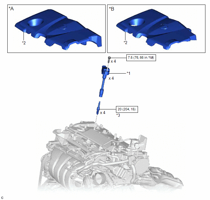
COMPONENTS
ILLUSTRATION
|
*A | for 2WD |
*B | for AWD |
|
*1 | IGNITION COIL ASSEMBLY |
*2 | NO. 1 ENGINE COVER SUB-ASSEMBLY |
|
*3 | SPARK PLUG |
- | - |
.png) |
N*m (kgf*cm, ft.*lbf): Specified torque |
- | - |
READ NEXT:
 Removal
REMOVAL CAUTION / NOTICE / HINT
The necessary procedures (adjustment, calibration, initialization, or registration) that must be performed after parts are removed and installed, or replaced during s
Installation
INSTALLATION CAUTION / NOTICE / HINT
NOTICE: This procedure includes the installation of small-head bolts. Refer to Small-Head Bolts of Basic Repair Hint to identify the small-head bolts.
Click he
Air Conditioning Filter
ComponentsCOMPONENTS ILLUSTRATION
*1 AIR FILTER COVER PLATE
*2 CLEAN AIR FILTER
*3 LOWER INSTRUMENT COVER LH
*4 AIR FILTER CASE
*5 AIR FILTER SUB-ASSEMB
SEE MORE:
Components
COMPONENTS ILLUSTRATION
*1 FRONT AXLE ASSEMBLY
*2 FRONT LOWER BALL JOINT ASSEMBLY
*3 COTTER PIN
- -
Tightening torque for "Major areas involving basic vehicle performance such as moving/turning/stopping" : N*m (kgf*cm, ft.*lbf)
● Non
Components
COMPONENTS ILLUSTRATION
*A for Fold Down Seat Type
- -
*1 REAR CENTER SEAT OUTER BELT ASSEMBLY
*2 REAR SEAT CUSHION ASSEMBLY
*3 REAR SEAT CUSHION LOCK HOOK
*4 REAR SIDE SEATBACK ASSEMBLY RH
*5 REAR SEAT INNER BELT ASSEMBLY RH
*6
© 2023-2026 Copyright www.tocamry.com
