Toyota Camry (XV70): Air Conditioning Filter
Components
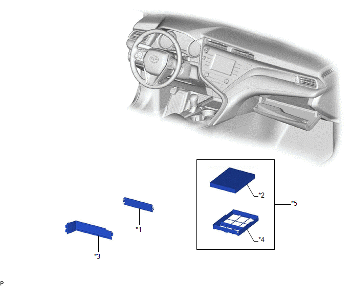
COMPONENTS
ILLUSTRATION
|
*1 | AIR FILTER COVER PLATE |
*2 | CLEAN AIR FILTER |
|
*3 | LOWER INSTRUMENT COVER LH |
*4 | AIR FILTER CASE |
|
*5 | AIR FILTER SUB-ASSEMBLY |
- | - |
Removal
REMOVAL
PROCEDURE
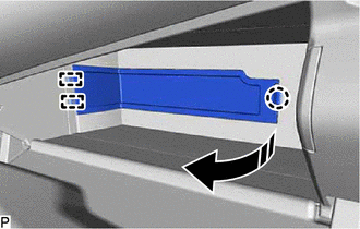
1. REMOVE LOWER INSTRUMENT COVER LH
(a) Open the lower instrument panel door.
(b) Disengage the claw and 2 guides to remove the lower instrument cover LH as shown in the illustration.
.png) |
Remove in this Direction |
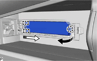
2. REMOVE AIR FILTER COVER PLATE
(a) Disengage the claw and 2 guides as indicated by the arrows, in the order shown in the illustration to remove the air filter cover plate.
|
|
Remove in this Direction (1) |
 |
Remove in this Direction (2) |
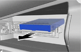
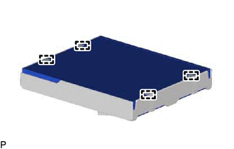
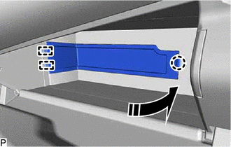
3. REMOVE CLEAN AIR FILTER
(a) Remove the air filter sub-assembly as shown in the illustration.
|
|
Remove in this Direction |
| (b) Disengage the 4 guides to remove the clean air filter from the air filter case. |
|
Installation
INSTALLATION
PROCEDURE
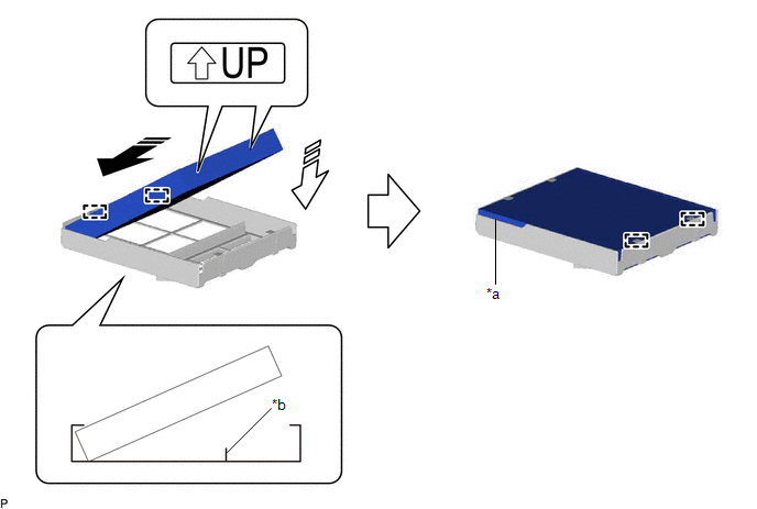
1. INSTALL CLEAN AIR FILTER
(a) Engage the 2 guides on the cutout side of the air filter case and then engage the 2 guides as shown in the illustration to install the clean air filter.
|
*a | Cutout |
*b | Rib |
.png) |
Install in this Direction (1) |
.png) |
Install in this Direction (2) |
NOTICE:
- Make sure that the "UP" marks are facing the correct direction before installing the clean air filter.
- Make sure that there is no clearance between the clean air filter and air filter case and that the clean air filter is not deformed.
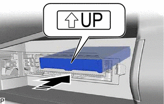
(b) Install the air filter sub-assembly as shown in the illustration.
|
|
Install in this Direction |
NOTICE:
Make sure that the "UP" mark is facing the correct direction before installing the air filter sub-assembly.
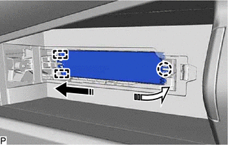
2. INSTALL AIR FILTER COVER PLATE
(a) Engage the 2 guides and claw as indicated by the arrows, in the order shown in the illustration to install the air filter cover plate.
|
|
Install in this Direction (1) |
|
|
Install in this Direction (2) |
3. INSTALL LOWER INSTRUMENT COVER LH
(a) Engage the 2 guides and claw to install the lower instrument cover LH as shown in the illustration.
|
|
Install in this Direction |
READ NEXT:
 Back-up Light Bulb
ComponentsCOMPONENTS ILLUSTRATION
*1 BACK-UP LIGHT BULB
*2 LUGGAGE COMPARTMENT DOOR COVER RemovalREMOVAL CAUTION / NOTICE / HINT
HINT:
Use the same procedure for the RH si
Brake Fluid
ComponentsCOMPONENTS ILLUSTRATION
*1 BRAKE MASTER CYLINDER RESERVOIR FILLER CAP ASSEMBLY
- - ILLUSTRATION
*A except 2-Pot Caliper
*B for 2-Pot Caliper
SEE MORE:
Components
COMPONENTS ILLUSTRATION
*1 FRONT DIFFERENTIAL CASE FRONT TAPERED ROLLER BEARING (INNER RACE)
*2 FRONT DIFFERENTIAL CASE FRONT TAPERED ROLLER BEARING (OUTER RACE)
*3 FRONT DIFFERENTIAL CASE REAR TAPERED ROLLER BEARING (INNER RACE)
*4 FRONT DIFFERENTIAL CASE REAR
Lost Communication with Wiper System LIN BUS (B1373)
DESCRIPTION The main body ECU (multiplex network body ECU) and windshield wiper motor assembly communicate via LIN communication. The main body ECU (multiplex network body ECU) stores this DTC if communication becomes abnormal.
DTC No. Detection Item
DTC Detection Condition
Trou
