Toyota Camry (XV70): Removal
REMOVAL
CAUTION / NOTICE / HINT
The necessary procedures (adjustment, calibration, initialization, or registration) that must be performed after parts are removed and installed, or replaced during spark plug removal/installation are shown below.
Necessary Procedures After Parts Removed/Installed/Replaced|
Replaced Part or Performed Procedure |
Necessary Procedure | Effect/Inoperative Function when Necessary Procedure not Performed |
Link |
|---|---|---|---|
| Inspection after repair |
|
|
NOTICE:
This procedure includes the removal of small-head bolts. Refer to Small-Head Bolts of Basic Repair Hint to identify the small-head bolts.
Click here .gif)
PROCEDURE
1. REMOVE NO. 1 ENGINE COVER SUB-ASSEMBLY
Click here
2. REMOVE IGNITION COIL ASSEMBLY
Click here
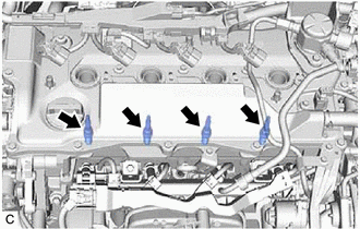
3. REMOVE SPARK PLUG
| (a) Remove the 4 spark plugs from the cylinder head sub-assembly. NOTICE: If a spark plug has been struck or dropped, replace it. HINT: Arrange the removed parts in the correct order. |
|
READ NEXT:
 Installation
INSTALLATION CAUTION / NOTICE / HINT
NOTICE: This procedure includes the installation of small-head bolts. Refer to Small-Head Bolts of Basic Repair Hint to identify the small-head bolts.
Click he
Air Conditioning Filter
ComponentsCOMPONENTS ILLUSTRATION
*1 AIR FILTER COVER PLATE
*2 CLEAN AIR FILTER
*3 LOWER INSTRUMENT COVER LH
*4 AIR FILTER CASE
*5 AIR FILTER SUB-ASSEMB
Back-up Light Bulb
ComponentsCOMPONENTS ILLUSTRATION
*1 BACK-UP LIGHT BULB
*2 LUGGAGE COMPARTMENT DOOR COVER RemovalREMOVAL CAUTION / NOTICE / HINT
HINT:
Use the same procedure for the RH si
SEE MORE:
Problem Symptoms Table
PROBLEM SYMPTOMS TABLE
HINT:
Use the table below to help determine the cause of problem symptoms. If multiple suspected areas are listed, the potential causes of the symptoms are listed in order of probability in the "Suspected Area" column of the table. Check each symptom by checking the susp
Installation
INSTALLATION CAUTION / NOTICE / HINT
CAUTION: After installing the luggage compartment door support assembly, use your hand to open and close the luggage door. Make sure the luggage door can open and close smoothly. PROCEDURE
1. INSTALL LUGGAGE COMPARTMENT DOOR SUPPORT ASSEMBLY
NOTICE:
