Toyota Camry (XV70): Removal
REMOVAL
CAUTION / NOTICE / HINT
The necessary procedures (adjustment, calibration, initialization, or registration) that must be performed after parts are removed and installed, or replaced during front lower ball joint assembly removal/installation are shown below.
Necessary Procedures After Parts Removed/Installed/Replaced|
Replaced Part or Performed Procedure |
Necessary Procedure | Effect/Inoperative Function when Necessary Procedure not Performed |
Link |
|---|---|---|---|
| Front wheel alignment adjustment |
|
| w/ Electric Parking Brake System:
w/o Electric Parking Brake System:
|
HINT:
- Use the same procedure for the RH side and LH side.
- The following procedure is for the LH side.
PROCEDURE
1. REMOVE FRONT AXLE ASSEMBLY
Click here .gif)
2. REMOVE FRONT LOWER BALL JOINT ASSEMBLY
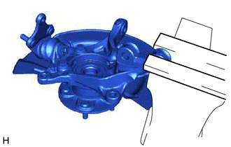
| (a) Secure the front axle assembly in a vise using aluminum plates. NOTICE: Do not overtighten the vise. |
|
| (b) Remove the cotter pin. |
|
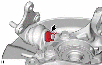
(c) Remove the nut.
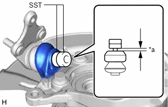
| (d) Install SST to the front lower ball joint assembly as shown in the illustration. SST: 09960-20010 09961-02050 NOTICE: Check that the clearance measurement between SST and the front axle assembly is 1 mm (0.0394 in.). |
|
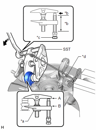
(e) Using SST, remove the front lower ball joint assembly from the front axle assembly as shown in the illustration.
SST: 09960-20010
09961-02010
09961-02050
|
*a | Center Nut |
|
*b | Molybdenum Grease Application Area |
|
*c | Place wrench here |
|
*d | String |
 |
Turn |
CAUTION:
Apply molybdenum grease to the threads and end of the SST bolt.
NOTICE:
- Be sure to tighten the string firmly to secure SST to the front axle assembly to prevent SST from falling off.
- Install SST with the center nut so that (A) and (B) shown in the illustration are parallel. Otherwise, the front lower ball joint dust cover may be damaged.
- Be sure to place a wrench on the part shown in the illustration.
- Do not damage the front lower ball joint dust cover.
- Do not damage the steering knuckle.
- Do not damage the front disc brake dust cover.
READ NEXT:
 Inspection
INSPECTION PROCEDURE 1. INSPECT FRONT LOWER BALL JOINT ASSEMBLY
(a) Inspect the turning torque of the ball joint. (1) Secure the front lower ball joint assembly in a vise using aluminum plates.
Installation
INSTALLATION CAUTION / NOTICE / HINT
HINT:
Use the same procedure for the RH side and LH side.
The following procedure is for the LH side.
PROCEDURE 1. INSTALL FRONT LOWER BALL JOINT ASS
SEE MORE:
Transmission Fluid Temperature Sensor "A" Circuit Short to Battery or Open (P071015)
DESCRIPTION The ATF temperature sensor converts the automatic transaxle fluid (ATF) temperature into a resistance value for use by the ECM.
The ECM applies voltage to the temperature sensor through terminal THO1 of the ECM.
The sensor resistance changes with the ATF temperature. As the temperatu
Cylinder 1 Injector "B" Circuit Open (P21CF13,P21D013-P21D413)
DESCRIPTION The D-4S system has two injection systems. One is an in-cylinder direct injection system that directly injects pressurized fuel into the combustion chamber. The other is an intake port injection system. The ECM determines the percentage of direct injection and port injection necessary in
