Toyota Camry (XV70): Removal
REMOVAL
CAUTION / NOTICE / HINT
The necessary procedures (adjustment, calibration, initialization, or registration) that must be performed after parts are removed and installed, or replaced during front lower No. 1 suspension arm sub-assembly removal/installation are shown below.
Necessary Procedures After Parts Removed/Installed/Replaced|
Replaced Part or Performed Procedure |
Necessary Procedure | Effect/Inoperative Function when Necessary Procedure not Performed |
Link |
|---|---|---|---|
| Front wheel alignment adjustment |
|
| w/ Electric Parking Brake System:
w/o Electric Parking Brake System:
|
|
Suspension, tires, etc. (The vehicle height changes because of suspension or tire replacement) |
Rear television camera assembly optical axis (Back camera position setting) |
Parking assist monitor system |
for Initialization: for Calibration:
|
| Panoramic view monitor system |
for Initialization: for Calibration:
|
HINT:
- Use the same procedure for the RH side and LH side.
- The following procedure is for the LH side.
PROCEDURE
1. REMOVE FRONT WHEEL
Click here
.gif)
2. REMOVE FRONT WHEEL OPENING EXTENSION PAD LH
for A25A-FKS: Click here
for 2GR-FKS: Click here
3. REMOVE FRONT WHEEL OPENING EXTENSION PAD RH
for A25A-FKS: Click here
for 2GR-FKS: Click here
4. REMOVE NO. 1 ENGINE UNDER COVER
for A25A-FKS: Click here
for 2GR-FKS: Click here
5. REMOVE NO. 2 ENGINE UNDER COVER ASSEMBLY (for A25A-FKS)
Click here
6. REMOVE REAR ENGINE UNDER COVER LH (for 2GR-FKS)
Click here
7. REMOVE FRONT FLOOR COVER LH
for A25A-FKS: Click here
for 2GR-FKS: Click here
8. REMOVE FRONT FENDER APRON SEAL LH
for A25A-FKS: Click here
for 2GR-FKS: Click here
9. REMOVE FRONT LOWER NO. 1 SUSPENSION ARM SUB-ASSEMBLY
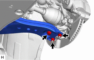
| (a) Remove the bolt and 2 nuts and separate the front lower No. 1 suspension arm sub-assembly from the front lower ball joint assembly. |
|
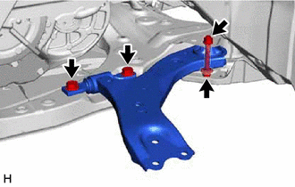
| (b) Remove the 3 bolts, nut and front lower No. 1 suspension arm sub-assembly from the front frame assembly. NOTICE: Because the nut has its own stopper, do not turn the nut. Loosen the bolt with the nut secured. |
|
(c) Remove the front lower arm bushing stopper from the front lower No. 1 suspension arm sub-assembly.
READ NEXT:
 Installation
INSTALLATION CAUTION / NOTICE / HINT
HINT:
Use the same procedure for the RH side and LH side.
The following procedure is for the LH side.
PROCEDURE 1. INSTALL FRONT LOWER NO. 1 SUSPENSI
Components
COMPONENTS ILLUSTRATION
*1 FRONT SHOCK ABSORBER WITH COIL SPRING
*2 FRONT SPEED SENSOR
*3 FRONT STABILIZER LINK ASSEMBLY
*4 FRONT FLEXIBLE HOSE
*5 STEER
SEE MORE:
Wheels
If a wheel is bent, cracked or heavily corroded, it should be
replaced. Otherwise, the tire may separate from the wheel or
cause a loss of handling control.
Wheel selection
When replacing wheels, care should be taken to ensure that they are
equivalent to those removed in load capacity, diameter
Parts Location
PARTS LOCATION ILLUSTRATION
*1 OUTER MIRROR SWITCH ASSEMBLY
*2 OUTER REAR VIEW MIRROR ASSEMBLY LH
*3 OUTER REAR VIEW MIRROR ASSEMBLY RH
*4 OUTER MIRROR LH
*5 OUTER MIRROR RH
*6 MIRROR SELECT AND SURFACE ADJUST SWITCH
*7 ENGIN
