Toyota Camry (XV70): Removal
REMOVAL
CAUTION / NOTICE / HINT
The necessary procedures (adjustment, calibration, initialization, or registration) that must be performed after parts are removed and installed, or replaced during rear suspension member sub-assembly removal/installation are shown below.
Necessary Procedures After Parts Removed/Installed/Replaced|
Replaced Part or Performed Procedure |
Necessary Procedure | Effect/Inoperative Function when Necessary Procedure not Performed |
Link |
|---|---|---|---|
| Rear wheel alignment adjustment |
|
|
|
|
Suspension, tires, etc. (The vehicle height changes because of suspension or tire replacement) |
Rear television camera assembly optical axis (Back camera position setting) |
Parking assist monitor system |
|
| Panoramic view monitor system |
| |
| Inspection After Repair |
|
|
CAUTION:
To prevent burns, do not touch the engine, exhaust pipe or other high temperature components while the engine is hot.
.png)
PROCEDURE
1. REMOVE REAR DIFFERENTIAL CARRIER ASSEMBLY
Click here
.gif)
2. REMOVE REAR NO. 1 DIFFERENTIAL MOUNT CUSHION
Click here
3. REMOVE REAR NO. 2 SUSPENSION ARM ASSEMBLY LH
Click here
4. REMOVE REAR NO. 2 SUSPENSION ARM ASSEMBLY RH
HINT:
Perform the same procedure as for the LH side.
5. REMOVE SPARE WHEEL COVER ASSEMBLY
Click here
6. REMOVE REAR SEAT CUSHION ASSEMBLY
Click here
7. REMOVE REAR SEAT CUSHION LOCK HOOK
Click here
8. REMOVE REAR SEATBACK ASSEMBLY LH
Click here
9. REMOVE REAR SEATBACK ASSEMBLY RH
Click here
10. REMOVE LUGGAGE COMPARTMENT TRIM INNER PAD
Click here
11. REMOVE REAR SUSPENSION MEMBER SUB-ASSEMBLY
| (a) Disconnect the connector and disengage the clamp. |
|
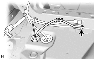
(b) Remove the grommet of the wire harness and pass the connector through the hole to the outside of the vehicle.
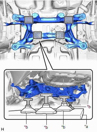
(c) Using an engine lifter and 4 attachments or equivalent tools, support the rear suspension member sub-assembly as shown in the illustration.
.png)
- The rear suspension member sub-assembly is a very heavy component. Make sure that it is supported securely.
- If the rear suspension member sub-assembly is not securely supported, it may drop, resulting in serious injury.
NOTICE:
Use attachments or equivalent tools to keep the rear suspension member sub-assembly level.
|
*a | Engine Lifter |
|
*b | Attachment |
.png) |
Attachment Placement Location |
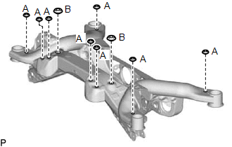
| (d) Remove the 2 bolts, 6 nuts, 2 rear suspension member lower stoppers, rear suspension member lower brace LH and rear suspension member lower brace RH. |
|
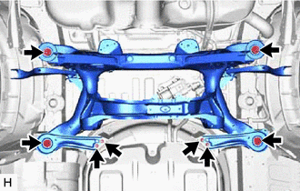
(e) Slowly lower the rear suspension member sub-assembly.
NOTICE:
When lowering the rear suspension member sub-assembly, be careful not to damage the vehicle body or other components installed to the vehicle.
(f) Remove the 4 rear suspension member cushions from the rear suspension member sub-assembly.
HINT:
Make sure to place an identification mark on the rear suspension member cushion so that they can be reinstalled to their original positions.
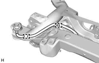
12. REMOVE WIRE HARNESS
|
(a) Disengage the 2 clamps and remove the wire harness from the rear suspension member sub-assembly. |
|
13. REMOVE REAR UPPER CONTROL ARM ASSEMBLY LH
Click here
14. REMOVE REAR UPPER CONTROL ARM ASSEMBLY RH
HINT:
Perform the same procedure as for the LH side.
15. REMOVE REAR SUSPENSION MEMBER FRONT BODY MOUNTING CUSHION (for LH Side)
| (a) Using a chisel and hammer, bend the 2 portions of the rear suspension member front body mounting cushion rib. NOTICE: Make sure to bend the 2 portions of the cushion rib until the claws of SST can fit securely. |
|
(b) Apply lubricant to the contact surfaces of the rear suspension member front body mounting cushion.
| (c) Install SST as shown in the illustration. SST: 09830-10010 09830-01010 09830-01040 09830-01050 SST: 09950-40011 09951-04010 09952-04010 09954-04010 09955-04061 09958-04011 NOTICE: Apply molybdenum grease to the threads and tip of the SST center bolt before use. |
|
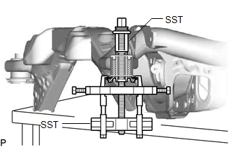
(d) Using SST, remove the rear suspension member front body mounting cushion while applying lubricant into the clearance between the rear suspension member front body mounting cushion and the rear suspension member sub-assembly.
SST: 09830-10010
09830-01010
09830-01040
09830-01050
SST: 09950-40011
09951-04010
09952-04010
09954-04010
09955-04061
09958-04011
NOTICE:
- Set the claws of SST into the rear suspension member sub-assembly securely as shown in the illustration.
- Tighten SST slowly and evenly.
- Be careful as the rear suspension member front body mounting cushion may fly out.
- The rear suspension member front body mounting cushion cannot be reused.
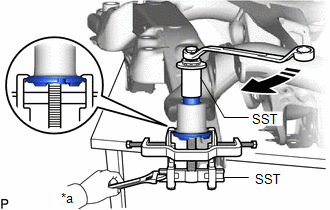
|
*a | Hold |
.png) |
Turn |
(e) Remove SST and the rear suspension member front body mounting cushion from the rear suspension member sub-assembly.
16. REMOVE REAR SUSPENSION MEMBER FRONT BODY MOUNTING CUSHION (for RH Side)
HINT:
Perform the same procedure as for the LH side.
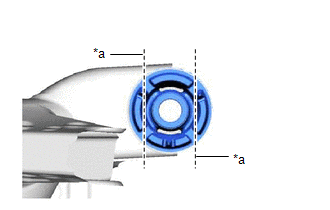
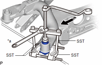
17. REMOVE REAR SUSPENSION MEMBER REAR BODY MOUNT CUSHION LH
| (a) Install SST as shown in the illustration. SST: 09950-00020 SST: 09950-00030 SST: 09950-60011 09951-00330 NOTICE: Apply molybdenum grease to the threads and tip of the SST center bolt before use. |
|
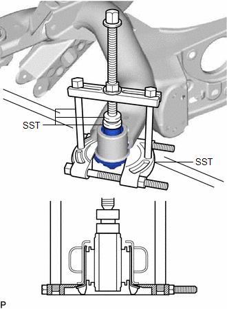
(b) Using SST, remove the rear suspension member rear body mount cushion LH while applying lubricant into the clearance between the rear suspension member rear body mount cushion LH and the rear suspension member sub-assembly.
SST: 09950-00020
SST: 09950-00030
SST: 09950-60011
09951-00330
NOTICE:
- Tighten SST slowly and evenly.
- Be careful as the rear suspension member rear body mount cushion LH may fly out.
- The rear suspension member rear body mount cushion LH cannot be reused.
|
*a | Hold |
|
|
Turn |
(c) Remove SST and the rear suspension member rear body mount cushion LH from the rear suspension member sub-assembly.
18. REMOVE REAR SUSPENSION MEMBER REAR BODY MOUNT CUSHION RH
HINT:
Perform the same procedure as for the LH side.
19. REMOVE HOLE PLUG
| (a) Remove the 10 hole plugs from the rear suspension member sub-assembly. HINT: There are 2 different shapes of hole plug. |
|
READ NEXT:
 Installation
INSTALLATION PROCEDURE 1. INSTALL HOLE PLUG
(a) Install the 10 hole plugs to the rear suspension member sub-assembly.
HINT: There are 2 different shapes of hole plug.
2. INS
Problem Symptoms Table
PROBLEM SYMPTOMS TABLE HINT: Use the table below to help determine the cause of problem symptoms. If multiple suspected areas are listed, the potential causes of the symptoms are listed in order of pr
SEE MORE:
Headlight switch
Operating instructions
Operating the switch turns on
the lights as follows:
For U.S.A.
The headlights, daytime
running lights and all the lights
listed below turn on and
off automatically.
(Vehicles without a
smart key system:
When the engine
switch is in the "ON"
position)
How To Proceed With Troubleshooting
CAUTION / NOTICE / HINT PRECAUTIONS WHEN TROUBLESHOOTING
NOTICE:
Because the order of diagnosis is important to allow correct diagnosis, make sure to begin troubleshooting using How to Proceed with Troubleshooting when CAN communication system related DTCs are output.
If the CAN communica
