Toyota Camry (XV70): Removal
REMOVAL
PROCEDURE
1. REMOVE FRONT WHEEL LH
Click here .gif)
2. REMOVE FRONT WHEEL OPENING EXTENSION PAD LH
HINT:
Use the same procedure as for the RH side.
Click here
3. REMOVE FRONT FENDER LINER LH
HINT:
Use the same procedure as for the RH side.
Click here
4. REMOVE COOL AIR INTAKE DUCT SEAL
Click here
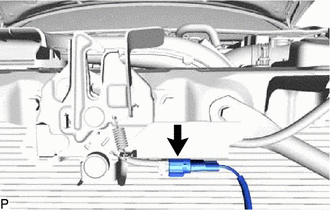
5. REMOVE HOOD LOCK ASSEMBLY
| (a) Disconnect the connector. |
|
| (b) Using a screwdriver with its tip wrapped with protective tape, remove the hood lock nut cap. |
|
.png)
| (c) Remove the 2 bolts and hood lock bolt. |
|
.png)
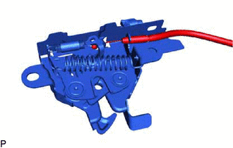
| (d) Disconnect the hood lock control cable assembly to remove the hood lock assembly. |
|
6. REMOVE FRONT DOOR SCUFF PLATE LH
Click here
7. REMOVE COWL SIDE TRIM SUB-ASSEMBLY LH
Click here
8. REMOVE NO. 1 INSTRUMENT PANEL UNDER COVER SUB-ASSEMBLY
Click here
9. DISCONNECT HOOD LOCK CONTROL LEVER SUB-ASSEMBLY
Click here
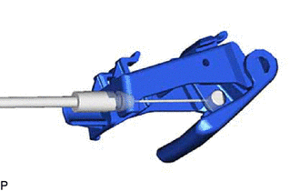
10. REMOVE HOOD LOCK CONTROL LEVER SUB-ASSEMBLY
| (a) Disconnect the hood lock control cable assembly to remove the hood lock control lever sub-assembly. |
|
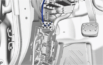
11. REMOVE HOOD LOCK CONTROL CABLE ASSEMBLY
| (a) Disengage the clamp. |
|
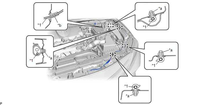
(b) Using a screwdriver, disengage the 4 clamps and grommet as shown in the illustration.
|
*1 | Hood Lock Control Cable Assembly |
- | - |
|
*a | Clamp |
*b | Grommet |
HINT:
Tape the screwdriver tip before use.
(c) Pull the hood lock control cable assembly from the engine compartment to remove it.
READ NEXT:
 Installation
INSTALLATION PROCEDURE 1. INSTALL HOOD LOCK CONTROL CABLE ASSEMBLY
(a) Pass the hood lock control cable assembly into the engine compartment.
(b) Engage the grommet. (c) Engage the 4 clamps to i
Components
COMPONENTS ILLUSTRATION
*1 LUGGAGE COMPARTMENT DOOR COVER
*2 LUGGAGE COMPARTMENT DOOR HINGE COVER LH
*3 LUGGAGE COMPARTMENT DOOR HINGE COVER RH
*4 LUGGAGE C
SEE MORE:
Inspection
INSPECTION PROCEDURE 1. INSPECT REAR STABILIZER LINK ASSEMBLY
(a) Inspect the turning torque of the ball joint.
(1) Secure the rear stabilizer link assembly in a vise using aluminum plates.
NOTICE: Do not overtighten the vise. (2) Install the nut to the rear stabilizer link assembly stud.
(
Installation
INSTALLATION CAUTION / NOTICE / HINT
HINT:
Use the same procedure for the RH side and LH side.
The following procedure is for the LH side.
PROCEDURE 1. INSTALL FRONT AXLE HUB SUB-ASSEMBLY
(a) Secure the steering knuckle between aluminum plates in a vise. NOTICE:
Do not overtighten
