Toyota Camry (XV70): Removal
REMOVAL
CAUTION / NOTICE / HINT
The necessary procedures (adjustment, calibration, initialization, or registration) that must be performed after parts are removed and installed, or replaced during outer rear view mirror cover removal/installation are shown below.
Necessary Procedure After Parts Removed/Installed/Replaced|
Replaced Part or Performed Procedure |
Necessary Procedure | Effect/Inoperative Function when Necessary Procedure not Performed |
Link |
|---|---|---|---|
| *1: Applies only for when removing and installing or replacing the rear television camera assembly. | |||
| Side television camera view adjustment |
Panoramic View Monitor System |
|
Replacement or removal and installation of 2 or more parts:
|
| ||
HINT:
- Use the same procedure for the RH side and LH side.
- The following procedure is for the LH side.
PROCEDURE
1. REMOVE OUTER MIRROR (for Type A)
Click here .gif)
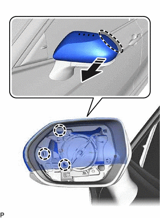
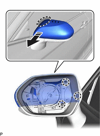
2. REMOVE OUTER MIRROR COVER WITH OUTER MIRROR HOLE COVER (for Type A)
(a) w/o Panoramic View Monitor System:

.png) |
Place Hand Here |
.png) |
Pull in this Direction |
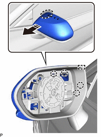
(1) Pull the outer mirror cover with outer mirror hole cover as shown in the illustration to disengage the 3 claws and guide.
NOTICE:
As the claws and guide may be damaged, make sure not to apply force in any direction other than shown in the illustration.
HINT:
If it is difficult to disengage the claws, disengage them using a screwdriver with its tip wrapped with protective tape.
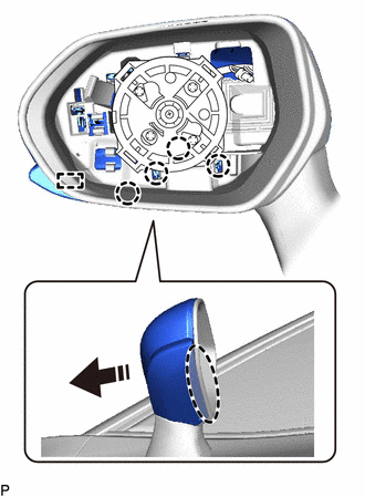
(2) Pull the outer mirror cover with outer mirror hole cover as shown in the illustration to disengage the 4 claws and guide.
|
|
Place Hand Here |
|
|
Pull in this Direction |
NOTICE:
As the claws and guide may be damaged, make sure not to apply force in any direction other than shown in the illustration.
HINT:
If it is difficult to disengage the claws, disengage them using a screwdriver with its tip wrapped with protective tape.
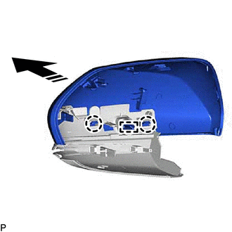
(3) Pull the outer mirror cover with outer mirror hole cover as shown in the illustration to disengage the 4 claws and guide and remove the outer mirror cover with outer mirror hole cover.
|
|
Place Hand Here |
|
|
Remove in this Direction |
NOTICE:
As the claws and guides may be damaged, make sure not to apply force in any direction other than shown in the illustration.
HINT:
If it is difficult to disengage the claws, disengage them using a screwdriver with its tip wrapped with protective tape.
3. REMOVE OUTER MIRROR COVER (for Type A)
(a) w/o Panoramic View Monitor System:
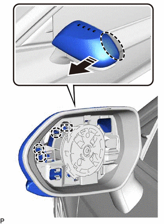
(1) Disengage the 2 claws and guide to remove the outer mirror cover as shown in the illustration.
|
|
Remove in this Direction |
(b) w/ Panoramic View Monitor System:
(1) Pull the outer mirror cover as shown in the illustration to disengage the 3 claws and guide.
NOTICE:
As the claws and guide may be damaged, make sure not to apply force in any direction other than shown in the illustration.
HINT:
If it is difficult to disengage the claws, disengage them using a screwdriver with its tip wrapped with protective tape.
|
|
Place Hand Here |
|
|
Pull in this Direction |
(2) Pull the outer mirror cover as shown in the illustration to disengage the 4 claws and guide.
NOTICE:
As the claws and guide may be damaged, make sure not to apply force in any direction other than shown in the illustration.
HINT:
If it is difficult to disengage the claws, disengage them using a screwdriver with its tip wrapped with protective tape.

|
|
Place Hand Here |
|
|
Pull in this Direction |
(3) Pull the outer mirror cover as shown in the illustration to disengage the 4 claws and guide.
NOTICE:
As the claws and guides may be damaged, make sure not to apply force in any direction other than shown in the illustration.
HINT:
If it is difficult to disengage the claws, disengage them using a screwdriver with its tip wrapped with protective tape.

|
|
Place Hand Here |
|
|
Remove in this Direction |
| (4) Disengage the 2 claws and guide to remove the outer mirror cover as shown in the illustration. |
|
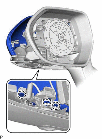
4. REMOVE OUTER MIRROR HOLE COVER WITH SIDE TELEVISION CAMERA ASSEMBLY (for Type A)
(a) w/ Panoramic View Monitor System:
| (1) Disengage the clamp. |
|
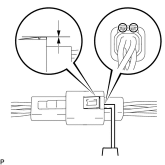
| (2) Insert a 0.9 mm (0.0354 in.) spark plug gap gauge or similar tool into the connector as shown in the illustration. NOTICE:
|
|
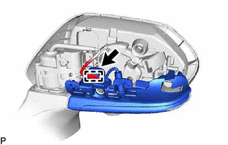
(3) Lift the claw and disconnect the connector to remove the outer mirror hole cover with side television camera assembly.
5. REMOVE SIDE TELEVISION CAMERA ASSEMBLY (for Type A)
w/ Panoramic View Monitor System:
Click here
6. REMOVE OUTER MIRROR (for Type B)
Click here
7. REMOVE OUTER MIRROR COVER (for Type B)
(a) Pull the outer mirror cover as shown in the illustration to disengage the 3 claws.
|
|
Place Hand Here |
|
|
Pull in this Direction |
NOTICE:
As the claws may be damaged, make sure not to apply force in any direction other than shown in the illustration.
HINT:
If it is difficult to disengage the claws, disengage them using a screwdriver with its tip wrapped with protective tape.
(b) Pull the outer mirror cover as shown in the illustration to disengage the 3 claws and remove the outer mirror cover.
|
|
Place Hand Here |
|
|
Pull in this Direction |
NOTICE:
As the claws may be damaged, make sure not to apply force in any direction other than shown in the illustration.
HINT:
If it is difficult to disengage the claws, disengage them using a screwdriver with its tip wrapped with protective tape.
READ NEXT:
 Installation
INSTALLATION CAUTION / NOTICE / HINT
HINT:
Use the same procedure for the RH side and LH side.
The following procedure is for the LH side.
PROCEDURE 1. INSTALL OUTER MIRROR HOLE COV
Components
COMPONENTS ILLUSTRATION
*A for Type A
*B for Type B
*1 OUTER MIRROR
- -
SEE MORE:
Fuel Rail Pressure Sensor (Low) Signal Stuck in Range (P107A2A,P107A64)
DESCRIPTION Refer to DTC P107A11. Click here
DTC No. Detection Item
DTC Detection Condition Trouble Area
MIL Memory
Note P107A2A
Fuel Rail Pressure Sensor (Low) Signal Stuck in Range
When target low pressure side fuel pressure changes, the change in fue
Components
COMPONENTS ILLUSTRATION
*1 COWL TOP VENTILATOR LOUVER SUB-ASSEMBLY
*2 FRONT FENDER TO COWL SIDE SEAL LH
*3 FRONT FENDER TO COWL SIDE SEAL RH
*4 FRONT WIPER ARM AND BLADE ASSEMBLY LH
*5 FRONT WIPER ARM AND BLADE ASSEMBLY RH
*6 FRONT WIPE
