Toyota Camry (XV70): Installation
INSTALLATION
CAUTION / NOTICE / HINT
HINT:
- Use the same procedure for the RH side and LH side.
- The following procedure is for the LH side.
PROCEDURE
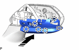
1. INSTALL OUTER MIRROR HOLE COVER ASSEMBLY (for Type A)
(a) w/o Panoramic View Monitor System:
(1) Engage the guide and 5 claws to install the outer mirror hole cover assembly as shown in the illustration.
.png) |
Install in this Direction |
2. INSTALL SIDE TELEVISION CAMERA ASSEMBLY (for Type A)
w/ Panoramic View Monitor System:
Click here
.gif)
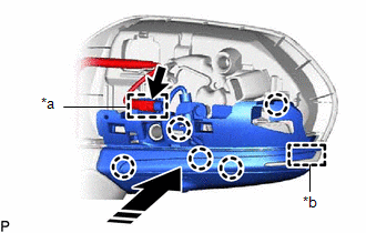
3. INSTALL OUTER MIRROR HOLE COVER WITH SIDE TELEVISION CAMERA ASSEMBLY (for Type A)
(a) w/ Panoramic View Monitor System:
(1) Engage the guide and 5 claws to install the outer mirror hole cover assembly as shown in the illustration.
|
*a | Clamp |
|
*b | Guide |
|
|
Install in this Direction |
(2) Connect the connector.
(3) Engage the clamp.
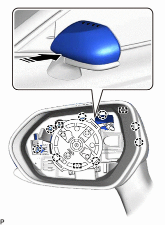
4. INSTALL OUTER MIRROR COVER (for Type A)
(a) Engage the 3 guides and 8 claws to install the outer mirror cover as shown in the illustration.
|
|
Install in this Direction |
5. INSTALL OUTER MIRROR (for Type A)
Click here
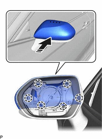
6. INSTALL OUTER MIRROR COVER (for Type B)
(a) Engage the 6 claws to install the outer mirror cover as shown in the illustration.
|
|
Install in this Direction |
7. INSTALL OUTER MIRROR (for Type B)
Click here
8. PERFORM CALIBRATION (w/ Panoramic View Monitor System)
Click here
READ NEXT:
 Components
COMPONENTS ILLUSTRATION
*A for Type A
*B for Type B
*1 OUTER MIRROR
- -
Removal
REMOVAL CAUTION / NOTICE / HINT
HINT:
Use the same procedure for the RH side and LH side.
The following procedure is for the LH side.
PROCEDURE 1. REMOVE OUTER MIRROR (for Type A)
SEE MORE:
Installation
INSTALLATION PROCEDURE 1. TEMPORARILY TIGHTEN PROPELLER WITH CENTER BEARING SHAFT ASSEMBLY
(a) When reusing a propeller with center bearing shaft assembly and rear differential carrier assembly:
(1) Align the matchmarks on the rear differential carrier assembly and propeller with center bea
Confirm Cellular Phone Functionality
PROCEDURE
1. CHECK CUSTOMER'S CELLULAR PHONE COMPATIBILITY
(a) Check if the cellular phone is compatible (Refer to http://www.toyota.com/Entune/).
Result Proceed to
Cellular phone is compatible.
A Cellular phone is not compatible.
B HINT: It is impo
