
Toyota Camry (XV70): Removal
REMOVAL
CAUTION / NOTICE / HINT
HINT:
- Use the same procedure for the RH side and LH side.
- The following procedure is for the LH side.
PROCEDURE
1. REMOVE OUTER MIRROR (for Type A)
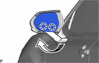
(a) Apply protective tape to the areas shown in the illustration.
.png) |
Protective Tape |
.png) |
Move in this Direction |
(b) Push the upper part of the mirror surface and tilt it.
(c) Using a moulding remover, disengage the 2 claws on the lower part of the outer mirror as shown in the illustration.
NOTICE:
Do not push the outer mirror with excessive force. Doing so may cause the actuator to come off or break the mirror surface.
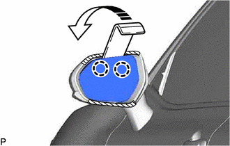
(d) Push the lower part of the mirror surface and tilt it.
(e) w/o Blind Spot Monitor System:
(1) Using a moulding remover, disengage the 2 claws on the upper part of the outer mirror as shown in the illustration to remove the outer mirror.
NOTICE:
Do not push the outer mirror with excessive force. Doing so may cause the actuator to come off or break the mirror surface.
|
|
Move in this Direction |
(f) w/ Blind Spot Monitor System:
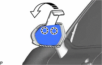
(1) Using a moulding remover, disengage the 2 claws on the upper part of the outer mirror as shown in the illustration.
|
|
Move in this Direction |
NOTICE:
Do not push the outer mirror with excessive force. Doing so may cause the actuator to come off or break the mirror surface.
| (2) Disconnect the connector. |
|
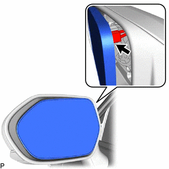
(3) Disengage the claw as shown in the illustration.
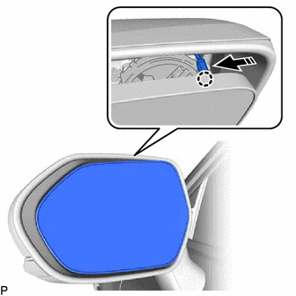
|
|
Push in this Direction |
| (4) Disengage the clamp. |
|
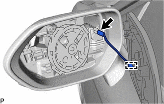
(5) Disconnect the connector to remove the outer mirror.
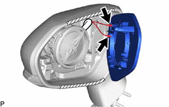
2. REMOVE OUTER MIRROR (for Type B)
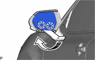
|
|
Protective Tape |
|
|
Move in this Direction |
(a) Apply protective tape to the areas shown in the illustration.
(b) Push the upper part of the mirror surface and tilt it.
(c) Using a moulding remover, disengage the 2 claws on the lower part of the outer mirror as shown in the illustration.
NOTICE:
Do not push the outer mirror with excessive force. Doing so may cause the actuator to come off or break the mirror surface.
(d) Push the lower part of the mirror surface and tilt it.
(e) Using a moulding remover, disengage the 2 claws on the upper part of the outer mirror as shown in the illustration.
NOTICE:
Do not push the outer mirror with excessive force. Doing so may cause the actuator to come off or break the mirror surface.
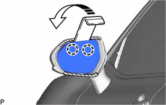
|
|
Move in this Direction |
| (f) Disconnect the 2 connectors to remove the outer mirror. |
|
READ NEXT:
 Inspection
INSPECTION PROCEDURE 1. INSPECT OUTER MIRROR RH
(a) Check the outer mirror heater operation. (w/ Mirror Heater)
(1) Measure the resistance according to the value(s) in the table below.
Installation
INSTALLATION CAUTION / NOTICE / HINT
HINT:
Use the same procedure for the RH side and LH side.
The following procedure is for the LH side.
PROCEDURE 1. INSTALL OUTER MIRROR (for Typ
SEE MORE:
Left Rear Wheel Speed Sensor Supply Voltage Circuit Short to Ground or Open (C14E614)
DESCRIPTION Refer to DTC C050C12 Click here
DTC No. Detection Item
DTC Detection Condition Trouble Area
C14E614 Left Rear Wheel Speed Sensor Supply Voltage Circuit Short to Ground or Open
An open or short in the speed sensor power supply circuit is detected for 0.1
Key-off Operation Function Operates even if Operating Conditions are not Satisfied
DESCRIPTION According to the panoramic moon roof switch (roof console box sub-assembly) operation, the sliding roof ECU (sliding roof drive gear assembly) or roof sunshade ECU (sliding roof drive gear assembly) operates its built-in motor. Using the panoramic moon roof switch (roof console box sub-a
