
Toyota Camry (XV70): Removal
REMOVAL
CAUTION / NOTICE / HINT
The necessary procedures (adjustment, calibration, initialization or registration) that must be performed after parts are removed and installed, or replaced during No. 1 cooler thermistor removal/installation are shown below.
Necessary Procedure After Parts Removed/Installed/Replaced|
Replaced Part or Performed Procedure |
Necessary Procedure | Effect/Inoperative Function when Necessary Procedure not Performed |
Link |
|---|---|---|---|
|
Disconnect cable from negative battery terminal |
Perform steering sensor zero point calibration |
Lane Tracing Assist System |
|
|
Pre-collision System | |||
|
Memorize steering angle neutral point |
Parking Assist Monitor System |
| |
|
Panoramic View Monitor System |
| ||
|
Steering sensor |
| Parking Assist Monitor System |
|
CAUTION:
Some of these service operations affect the SRS airbag system. Read the precautionary notices concerning the SRS airbag system before servicing.
Click here .gif)
.png)
PROCEDURE
1. REMOVE BLOWER ASSEMBLY
Click here
2. REMOVE AIR CONDITIONING HARNESS ASSEMBLY
Click here
3. REMOVE NO. 1 AIR CONDITIONING RADIATOR DAMPER SERVO SUB-ASSEMBLY
Click here
4. REMOVE HEATER PIPE GROMMET
Click here
5. REMOVE HEATER CLAMP
Click here
6. REMOVE HEATER RADIATOR UNIT SUB-ASSEMBLY
Click here
7. REMOVE GROMMET SUB-ASSEMBLY
Click here
8. REMOVE COOLER EXPANSION VALVE
Click here
9. REMOVE NO. 1 COOLER EVAPORATOR SUB-ASSEMBLY
Click here
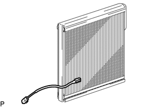
10. REMOVE NO. 1 COOLER THERMISTOR
| (a) Remove the No. 1 cooler thermistor. |
|
READ NEXT:
SEE MORE:
 Rear Power Window RH Auto Up / Down Function does not Operate with Rear Power Window Switch RH
DESCRIPTION If the manual up and down functions operate normally but the auto up and down functions do not, the power window control system may be in fail-safe mode.
If power window initialization has not been performed, the auto up and down functions will not operate.
Click here WIRING DIAG
Vehicle Speed Signal Circuit between Navigation ECU and Combination Meter
DESCRIPTION The navigation ECU receives a vehicle speed signal from the combination meter assembly.
HINT:
A voltage of 12 V or 5 V is output from each ECU and then input to the combination meter assembly. The signal is changed to a pulse signal at the transistor in the combination meter assemb
