
Toyota Camry (XV70): Removal
REMOVAL
PROCEDURE
1. REMOVE NO. 1 METER HOOD CLUSTER
Click here 
2. REMOVE LOWER INSTRUMENT PANEL FINISH PANEL ASSEMBLY
Click here
3. REMOVE LOWER CENTER INSTRUMENT PANEL FINISH PANEL
Click here
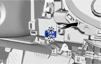
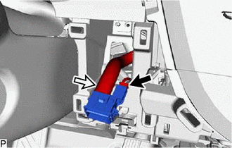
4. REMOVE COOLER (ROOM TEMP. SENSOR) THERMISTOR
 |
Remove in this Direction |
(a) Disengage the 2 claws as shown in the illustration.
| (b) Disconnect the connector and aspirator to remove the cooler (room temp. sensor) thermistor. |
|
READ NEXT:
 Inspection
INSPECTION PROCEDURE 1. INSPECT COOLER (ROOM TEMP. SENSOR) THERMISTOR
(a) Measure the resistance according to the value(s) in the table below.
Standard Resistance:
Tester Connection Co
Installation
INSTALLATION PROCEDURE 1. INSTALL COOLER (ROOM TEMP. SENSOR) THERMISTOR
(a) Connect the connector and aspirator. (b) Engage the 2 claws to install the cooler (room temp. sensor) thermistor as shown i
SEE MORE:
Components
COMPONENTS ILLUSTRATION
*1 FRONT DISC BRAKE ANTI-SQUEAL SHIM KIT
*2 FRONT DISC BRAKE PAD
*3 FRONT DISC BRAKE CYLINDER ASSEMBLY
*4 FRONT DISC BRAKE PAD WEAR INDICATOR PLATE
*5 FRONT NO. 1 DISC BRAKE ANTI-SQUEAL SHIM
*6 FRONT NO. 2 DISC BRAKE ANT
Engine Switch Illumination Circuit
DESCRIPTION The illuminated entry system controls the engine switch illumination. WIRING DIAGRAM
CAUTION / NOTICE / HINT
NOTICE: Before replacing the certification ECU (smart key ECU assembly), refer to Registration.*
Click here
*: w/ Smart Key System
PROCEDURE
1. PERFORM ACTIV
© 2023-2026 Copyright www.tocamry.com
