
Toyota Camry (XV70): Removal
REMOVAL
CAUTION / NOTICE / HINT
The necessary procedures (adjustment, calibration, initialization, or registration) that must be performed after parts are removed and installed, or replaced during automatic light control sensor removal/installation are shown below.
Necessary Procedure After Parts Removed/Installed/Replaced|
Replaced Part or Performed Procedure |
Necessary Procedure | Effect/Inoperative Function when Necessary Procedure not Performed |
Link |
|---|---|---|---|
|
Disconnect cable from negative battery terminal |
Perform steering sensor zero point calibration |
Lane Tracing Assist System |
|
|
Pre-collision System | |||
|
Memorize steering angle neutral point |
Parking Assist Monitor System |
| |
|
Panoramic View Monitor System |
|
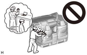
CAUTION:
Some of these service operations affect the SRS airbag system. Read the precautionary notices concerning the SRS airbag system before servicing.
Click here 
PROCEDURE
1. REMOVE INSTRUMENT PANEL SAFETY PAD SUB-ASSEMBLY
Click here
2. REMOVE NO. 1 SIDE DEFROSTER NOZZLE DUCT
Click here
3. REMOVE NO. 2 SIDE DEFROSTER NOZZLE DUCT
Click here
4. REMOVE DEFROSTER NOZZLE ASSEMBLY
Click here
5. REMOVE AUTOMATIC LIGHT CONTROL SENSOR
| (a) Disconnect the connector. |
|
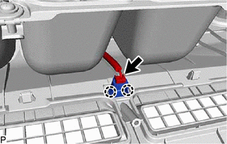
(b) Disengage the 2 claws to remove the automatic light control sensor.
READ NEXT:
 Inspection
INSPECTION PROCEDURE 1. INSPECT AUTOMATIC LIGHT CONTROL SENSOR
(a) Disconnect the M1 automatic light control sensor connector.
*a Front view of wire harness connector
Installation
INSTALLATION PROCEDURE 1. INSTALL AUTOMATIC LIGHT CONTROL SENSOR
(a) Engage the 2 claws to install the automatic light control sensor. (b) Connect the connector.
2. INSTALL DEFROSTER NOZZLE ASSEMBLY
SEE MORE:
Installation
INSTALLATION CAUTION / NOTICE / HINT
HINT:
Use the same procedure for the RH side and LH side.
The following procedure is for the LH side.
PROCEDURE 1. INSTALL FRONT DOOR COURTESY LIGHT SWITCH ASSEMBLY
(a) Connect the connector. (b) Using a T30 "TORX" socket wrench, install the front door co
Left Front Wheel Speed Sensor Signal Stuck High (C050024)
DESCRIPTION Refer to DTC C050012 Click here
DTC No. Detection Item
DTC Detection Condition Trouble Area
C050024 Left Front Wheel Speed Sensor Signal Stuck High
The speed sensor signal is not within the specified range for 5 seconds or more.
Front speed sensor
