Toyota Camry (XV70): Sensor (Motor) Failure (B2341,B2344)
DESCRIPTION
When the sliding roof ECU (sliding roof drive gear assembly) or roof sunshade ECU (sliding roof drive gear assembly) detects a motor malfunction and the sliding roof and roof sunshade operation is stopped, DTC B2341 is stored.
When the sliding roof ECU (sliding roof drive gear assembly) or roof sunshade ECU (sliding roof drive gear assembly) detects a gear position malfunction and the sliding roof and roof sunshade operation is stopped, DTC B2344 is stored.
Sliding Roof|
DTC No. | Detection Item |
DTC Detection Condition |
Trouble Area |
|---|---|---|---|
|
B2341 | Sensor (Motor) Failure |
Sensor (motor) failure (When the sliding roof ECU (sliding roof drive gear assembly) enters fail-safe mode due to a problem with the motor) |
|
| B2344 |
Position Failure | Position failure (When the sliding roof ECU (sliding roof drive gear assembly) enters fail-safe mode due to a problem with the gear position) |
|
|
DTC No. | Detection Item |
DTC Detection Condition |
Trouble Area |
|---|---|---|---|
|
B2341 | Sensor (Motor) Failure |
Sensor (motor) failure (When the roof sunshade ECU (sliding roof drive gear assembly) enters fail-safe mode due to a problem with the motor) |
|
| B2344 |
Position Failure | Position failure (When the roof sunshade ECU (sliding roof drive gear assembly) enters fail-safe mode due to a problem with the gear position) |
|
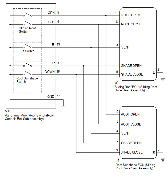
WIRING DIAGRAM
CAUTION / NOTICE / HINT
NOTICE:
- If the sliding roof ECU (sliding roof drive gear assembly) or roof sunshade ECU (sliding roof drive gear assembly) is removed and reinstalled or replaced, the sliding roof ECU (sliding roof drive gear assembly) or roof sunshade ECU (sliding roof drive gear assembly) must be initialized.
Click here
.gif)
- DTCs B2341 and B2344 are stored in the sliding roof ECU (sliding roof drive gear assembly) and roof sunshade ECU (sliding roof drive gear assembly).
PROCEDURE
|
1. | CHECK FOR DTC |
(a) Clear the DTCs.
Click here
(b) Check for DTCs.
Click here
OK:
DTCs B2341 and B2344 are not output.
| OK | .gif) |
USE SIMULATION METHOD TO CHECK
|
|
.gif)
|
2. | CHECK DTC OUTPUT |
(a) Check the parts from which this DTC has been output.
|
Result | Proceed to |
|---|---|
|
DTC output from sliding roof ECU (sliding roof drive gear assembly) |
A |
| DTC output from roof sunshade ECU (sliding roof drive gear assembly) |
B |
| B | |
GO TO STEP 9 |
|
|
3. | CHECK SLIDING ROOF OPERATION |
(a) Check the sliding roof auto operation function.
Click here
OK:
Auto operation function operates normally.
| NG | |
GO TO STEP 5 |
|
|
4. | CHECK DTC OUTPUT |
(a) Clear the DTCs.
Click here
(b) Check for DTCs.
Body Electrical > Sliding Roof > Trouble CodesOK:
DTCs B2341 and B2344 are not output.
| OK | |
USE SIMULATION METHOD TO CHECK
|
| NG | |
REPLACE SLIDING ROOF ECU (SLIDING ROOF DRIVE GEAR ASSEMBLY)
|
|
5. | INITIALIZE SLIDING ROOF ECU (SLIDING ROOF DRIVE GEAR ASSEMBLY) |
(a) Check that the sliding roof ECU (sliding roof drive gear assembly) can be initialized.
Click here
OK:
Sliding roof ECU (sliding roof drive gear assembly) can be initialized.
| NG | |
GO TO STEP 7 |
|
|
6. | CHECK DTC OUTPUT |
(a) Clear the DTCs.
Click here
(b) Check for DTCs.
Body Electrical > Sliding Roof > Trouble CodesOK:
DTCs B2341 and B2344 are not output.
| OK | |
END (MALFUNCTION DUE TO INITIALIZATION FAILURE) |
| NG | |
REPLACE SLIDING ROOF ECU (SLIDING ROOF DRIVE GEAR ASSEMBLY)
|
|
7. | CHECK HARNESS AND CONNECTOR (SLIDING ROOF ECU (SLIDING ROOF DRIVE GEAR ASSEMBLY) - PANORAMIC MOON ROOF SWITCH (ROOF CONSOLE BOX SUB-ASSEMBLY) AND BODY GROUND) |
(a) Disconnect the q1 sliding roof ECU (sliding roof drive gear assembly) connector.
(b) Disconnect the V14 panoramic moon roof switch (roof console box sub-assembly) connector.
(c) Disconnect the q2 roof sunshade ECU (sliding roof drive gear assembly) connector.
(d) Measure the resistance according to the value(s) in the table below.
Standard Resistance:
|
Tester Connection | Condition |
Specified Condition |
|---|---|---|
|
q1-8 (ROOF CLOSE) - V14-4 (CLS) |
Always | Below 1 Ω |
|
q1-8 (ROOF CLOSE) or V14-4 (CLS) - Body ground |
Always | 10 kΩ or higher |
|
q1-10 (ROOF OPEN) - V14-5 (OPN) |
Always | Below 1 Ω |
|
q1-10 (ROOF OPEN) or V14-5 (OPN) - Body ground |
Always | 10 kΩ or higher |
|
q1-4 (VENT) - V14-19 (B) |
Always | Below 1 Ω |
|
q1-4 (VENT) or V14-19 (B) - Body ground |
Always | 10 kΩ or higher |
|
q1-5 (SHADE OPEN) - V14-3 (UP) |
Always | Below 1 Ω |
|
q1-5 (SHADE OPEN) or V14-3 (UP) - Body ground |
Always | 10 kΩ or higher |
|
q1-9 (SHADE CLOSE) - V14-18 (DOWN) |
Always | Below 1 Ω |
|
q1-9 (SHADE CLOSE) or V14-18 (DOWN) - Body ground |
Always | 10 kΩ or higher |
|
q1-2 (E) - Body ground |
Always | Below 1 Ω |
|
V14-15 (GND) - Body ground |
Always | Below 1 Ω |
| NG | |
REPAIR OR REPLACE HARNESS OR CONNECTOR |
|
|
8. | INSPECT PANORAMIC MOON ROOF SWITCH (ROOF CONSOLE BOX SUB-ASSEMBLY) |
(a) Remove the panoramic moon roof switch (roof console box sub-assembly).
Click here
(b) Inspect the panoramic moon roof switch (roof console box sub-assembly).
Click here
| OK | |
REPLACE SLIDING ROOF ECU (SLIDING ROOF DRIVE GEAR ASSEMBLY)
|
| NG | |
REPLACE PANORAMIC MOON ROOF SWITCH (ROOF CONSOLE BOX SUB-ASSEMBLY)
|
|
9. | CHECK ROOF SUNSHADE OPERATION |
(a) Check the roof sunshade auto operation function.
Click here
OK:
Auto operation function operates normally.
| NG | |
GO TO STEP 11 |
|
|
10. | CHECK DTC OUTPUT |
(a) Clear the DTCs.
Click here
(b) Check for DTCs.
Body Electrical > Sliding Sunshade > Trouble CodesOK:
DTCs B2341 and B2344 are not output.
| OK | |
USE SIMULATION METHOD TO CHECK
|
| NG | |
REPLACE ROOF SUNSHADE ECU (SLIDING ROOF DRIVE GEAR ASSEMBLY)
|
|
11. | INITIALIZE ROOF SUNSHADE ECU (SLIDING ROOF DRIVE GEAR ASSEMBLY) |
(a) Check that the roof sunshade ECU (sliding roof drive gear assembly) can be initialized.
Click here
OK:
Roof sunshade ECU (sliding roof drive gear assembly) can be initialized.
| NG | |
GO TO STEP 13 |
|
|
12. | CHECK DTC OUTPUT |
(a) Clear the DTCs.
Click here
(b) Check for DTCs.
Body Electrical > Sliding Sunshade > Trouble CodesOK:
DTCs B2341 and B2344 are not output.
| OK | |
END (MALFUNCTION DUE TO INITIALIZATION FAILURE) |
| NG | |
REPLACE ROOF SUNSHADE ECU (SLIDING ROOF DRIVE GEAR ASSEMBLY)
|
|
13. | CHECK HARNESS AND CONNECTOR (ROOF SUNSHADE ECU (SLIDING ROOF DRIVE GEAR ASSEMBLY) - PANORAMIC MOON ROOF SWITCH (ROOF CONSOLE BOX SUB-ASSEMBLY) AND BODY GROUND) |
(a) Disconnect the q2 roof sunshade ECU (sliding roof drive gear assembly) connector.
(b) Disconnect the V14 panoramic moon roof switch (roof console box sub-assembly) connector.
(c) Disconnect the q1 sliding roof ECU (sliding roof drive gear assembly) connector.
(d) Measure the resistance according to the value(s) in the table below.
Standard Resistance:
|
Tester Connection | Condition |
Specified Condition |
|---|---|---|
|
q2-8 (ROOF CLOSE) - V14-4 (CLS) |
Always | Below 1 Ω |
|
q2-8 (ROOF CLOSE) or V14-4 (CLS) - Body ground |
Always | 10 kΩ or higher |
|
q2-10 (ROOF OPEN) - V14-5 (OPN) |
Always | Below 1 Ω |
|
q2-10 (ROOF OPEN) or V14-5 (OPN) - Body ground |
Always | 10 kΩ or higher |
|
q2-4 (VENT) - V14-19 (B) |
Always | Below 1 Ω |
|
q2-4 (VENT) or V14-19 (B) - Body ground |
Always | 10 kΩ or higher |
|
q2-5 (SHADE OPEN) - V14-3 (UP) |
Always | Below 1 Ω |
|
q2-5 (SHADE OPEN) or V14-3 (UP) - Body ground |
Always | 10 kΩ or higher |
|
q2-9 (SHADE CLOSE) - V14-18 (DOWN) |
Always | Below 1 Ω |
|
q2-9 (SHADE CLOSE) or V14-18 (DOWN) - Body ground |
Always | 10 kΩ or higher |
|
q2-2 (E) - Body ground |
Always | Below 1 Ω |
|
V14-15 (GND) - Body ground |
Always | Below 1 Ω |
| NG | |
REPAIR OR REPLACE HARNESS OR CONNECTOR |
|
|
14. | INSPECT PANORAMIC MOON ROOF SWITCH (ROOF CONSOLE BOX SUB-ASSEMBLY) |
(a) Remove the panoramic moon roof switch (roof console box sub-assembly).
Click here
(b) Inspect the panoramic moon roof switch (roof console box sub-assembly).
Click here
| OK | |
REPLACE ROOF SUNSHADE ECU (SLIDING ROOF DRIVE GEAR ASSEMBLY)
|
| NG | |
REPLACE PANORAMIC MOON ROOF SWITCH (ROOF CONSOLE BOX SUB-ASSEMBLY)
|
READ NEXT:
 Switch Failure (B2342)
DESCRIPTION This DTC is stored when the sliding roof ECU (sliding roof drive gear assembly) or roof sunshade ECU (sliding roof drive gear assembly) detects that the panoramic moon roof switch (roof co
Position Initialization Incomplete (B2343)
DESCRIPTION This DTC is stored when the sliding roof ECU (sliding roof drive gear assembly) or roof sunshade ECU (sliding roof drive gear assembly) has not been initialized. Sliding Roof
DTC No
Motor Control Relay Stuck ON (B2345)
DESCRIPTION This DTC will be stored if the operation of the sliding roof or roof sunshade is suspended and a pulse input of 10 Hz or more is detected when the motor relay is off. Sliding Roof
D
SEE MORE:
Slip Indicator Light Remains ON
DESCRIPTION This procedure is for troubleshooting when the slip indicator light remains on but no DTCs are output.
The skid control ECU (brake actuator assembly) controls the slip indicator light in the combination meter assembly via CAN communication.
The slip indicator light blinks during VSC
Removal
REMOVAL CAUTION / NOTICE / HINT
The necessary procedures (adjustment, calibration, initialization, or registration) that must be performed after parts are removed and installed, or replaced during spark plug removal/installation are shown below. Necessary Procedures After Parts Removed/Installed/R
