Toyota Camry (XV70): Sensor (Motor) Failure (B2341,B2344)
DESCRIPTION
When the sliding roof ECU (sliding roof drive gear sub-assembly) detects a motor malfunction and the sliding roof operation is stopped, DTC B2341 is stored.
When the sliding roof ECU (sliding roof drive gear sub-assembly) detects a gear position malfunction and the sliding roof operation is stopped, DTC B2344 is stored.
|
DTC No. | Detection Item |
DTC Detection Condition |
Trouble Area |
|---|---|---|---|
|
B2341 | Sensor (Motor) Failure |
Sensor (motor) failure (The sliding roof ECU (sliding roof drive gear sub-assembly) enters fail-safe mode due to a problem with the motor) |
|
| B2344 |
Position Failure | Position failure (The sliding roof ECU (sliding roof drive gear sub-assembly) enters fail-safe mode due to a problem with the gear position) |
|
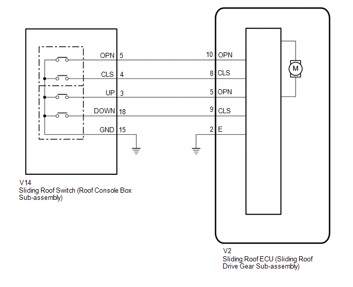
WIRING DIAGRAM
CAUTION / NOTICE / HINT
NOTICE:
- If the sliding roof ECU (sliding roof drive gear sub-assembly) is removed and reinstalled or replaced, the sliding roof ECU (sliding roof drive gear sub-assembly) must be initialized.
Click here
.gif)
PROCEDURE
|
1. | CHECK SLIDING ROOF OPERATION |
(a) Check the sliding roof auto operation.
Click here
OK:
Auto operation operates normally.
| NG | .gif) |
GO TO STEP 3 |
|
.gif)
|
2. | CHECK DTC OUTPUT |
(a) Clear the DTCs.
Body Electrical > Sliding Roof > Clear DTCs(b) Check for DTCs.
Body Electrical > Sliding Roof > Trouble CodesOK:
DTCs B2341 and B2344 are not output.
| OK | |
USE SIMULATION METHOD TO CHECK
|
| NG | |
REPLACE SLIDING ROOF ECU (SLIDING ROOF DRIVE GEAR SUB-ASSEMBLY)
|
|
3. | INITIALIZE SLIDING ROOF ECU (SLIDING ROOF DRIVE GEAR SUB-ASSEMBLY) |
(a) Check that the sliding roof ECU (sliding roof drive gear sub-assembly) can be initialized.
Click here
OK:
Sliding roof ECU (sliding roof drive gear sub-assembly) can be initialized.
| NG | |
GO TO STEP 5 |
|
|
4. | CHECK DTC OUTPUT |
(a) Clear the DTCs.
Body Electrical > Sliding Roof > Clear DTCs(b) Check for DTCs.
Body Electrical > Sliding Roof > Trouble CodesOK:
DTCs B2341 and B2344 are not output.
| OK | |
END (MALFUNCTION DUE TO INITIALIZATION FAILURE) |
| NG | |
REPLACE SLIDING ROOF ECU (SLIDING ROOF DRIVE GEAR SUB-ASSEMBLY)
|
|
5. | CHECK HARNESS AND CONNECTOR (SLIDING ROOF ECU (SLIDING ROOF DRIVE GEAR SUB-ASSEMBLY) - SLIDING ROOF SWITCH (ROOF CONSOLE BOX SUB-ASSEMBLY) AND BODY GROUND) |
(a) Disconnect the V14 sliding roof switch (roof console box sub-assembly) connector.
(b) Disconnect the V2 sliding roof ECU (sliding roof drive gear sub-assembly) connector.
(c) Measure the resistance according to the value(s) in the table below.
Standard Resistance:
|
Tester Connection | Condition |
Specified Condition |
|---|---|---|
|
V2-8 (CLS) - V14-4 (CLS) |
Always | Below 1 Ω |
|
V2-8 (CLS) or V14-4 (CLS) - Body ground |
Always | 10 kΩ or higher |
|
V2-10 (OPN) - V14-5 (OPN) |
Always | Below 1 Ω |
|
V2-10 (OPN) or V14-5 (OPN) - Body ground |
Always | 10 kΩ or higher |
|
V2-9 (CLS) - V14-18 (DOWN) |
Always | Below 1 Ω |
|
V2-9 (CLS) or V14-18 (DOWN) - Body ground |
Always | 10 kΩ or higher |
|
V2-5 (OPN) - V14-3 (UP) |
Always | Below 1 Ω |
|
V2-5 (OPN) or V14-3 (UP) - Body ground |
Always | 10 kΩ or higher |
|
V14-15 (GND) - Body ground |
Always | Below 1 Ω |
|
V2-2 (E) - Body ground |
Always | Below 1 Ω |
| NG | |
REPAIR OR REPLACE HARNESS OR CONNECTOR |
|
|
6. | INSPECT SLIDING ROOF SWITCH (ROOF CONSOLE BOX SUB-ASSEMBLY) |
(a) Remove the sliding roof switch (roof console box sub-assembly).
Click here
(b) Inspect the sliding roof switch (roof console box sub-assembly).
Click here
| OK | |
REPLACE SLIDING ROOF ECU (SLIDING ROOF DRIVE GEAR SUB-ASSEMBLY)
|
| NG | |
REPLACE SLIDING ROOF SWITCH (ROOF CONSOLE BOX SUB-ASSEMBLY)
|
READ NEXT:
 Switch Failure (B2342)
DESCRIPTION This DTC is stored when the sliding roof ECU (sliding roof drive gear sub-assembly) detects that the sliding roof switch (roof console box sub-assembly) is stuck for 30 seconds or more.
Position Initialization Incomplete (B2343)
DESCRIPTION This DTC is stored when the sliding roof ECU (sliding roof drive gear sub-assembly) has not been initialized.
DTC No. Detection Item
DTC Detection Condition
Trouble Ar
Remote Control System does not Operate
DESCRIPTION The main body ECU (multiplex network body ECU) receives remote control signals from the driver door key cylinder or electrical key transmitter sub-assembly. Then, the main body ECU (multip
SEE MORE:
Fail-safe Chart
FAIL-SAFE CHART
DTC Trouble Area
Parking Brake Indicator Light
Brake System Warning Light (Yellow)
Fail-safe Deactivation Condition
C059704 Skid control ECU (brake actuator assembly) internal malfunction
Normal Illuminates
After returning to normal cond
Inspection
INSPECTION PROCEDURE 1. INSPECT FUEL PUMP
(a) Measure the resistance according to the value(s) in the table below.
Standard Resistance:
Tester Connection Specified Condition
U - V 0.05 to 3.0 Ω
V - W 0.05 to 3.0 Ω
U - W 0.05 to 3.0 Ω
