Toyota Camry (XV70): Shift Lever Knob
Components
COMPONENTS
ILLUSTRATION
|
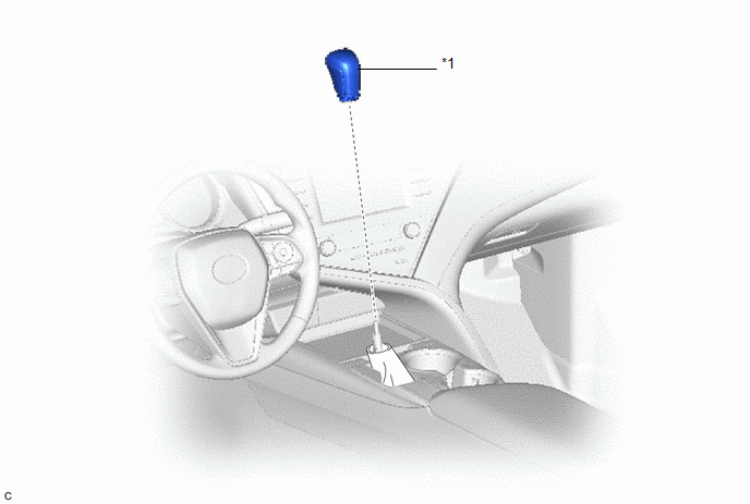
*1 | SHIFT LEVER KNOB SUB-ASSEMBLY |
- | - |
Removal
REMOVAL
PROCEDURE
1. REMOVE SHIFT LEVER KNOB SUB-ASSEMBLY
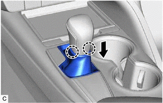
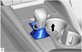
| (a) Disengage the 2 claws to disconnect the shifting hole cover sub-assembly as shown in the illustration. |
|
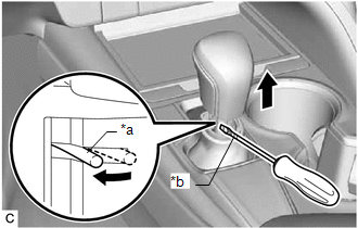
| (b) Using a screwdriver with its tip wrapped with protective tape, expand the left side of the clip and remove the shift lever knob sub-assembly from the transmission floor shift assembly as shown in the illustration. NOTICE: Be careful not to damage the shift lever knob sub-assembly. |
|
Installation
INSTALLATION
PROCEDURE
1. INSTALL SHIFT LEVER KNOB SUB-ASSEMBLY
| (a) Install the shift lever knob sub-assembly to the transmission floor shift assembly. |
|
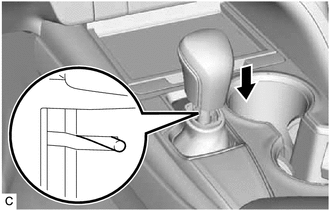
| (b) Engage the 2 claws to connect the shifting hole cover sub-assembly as shown in the illustration. NOTICE: Make sure that the shifting hole cover sub-assembly does not twist after installing the shift lever knob sub-assembly. |
|
READ NEXT:
 Components
COMPONENTS ILLUSTRATION
*1 STEERING WHEEL ASSEMBLY
*2 STEERING PAD SWITCH ASSEMBLY
*3 SHIFT PADDLE SWITCH (TRANSMISSION SHIFT SWITCH ASSEMBLY)
*4 NO. 1 SWITCH WIR
Removal
REMOVAL CAUTION / NOTICE / HINT
The necessary procedures (adjustment, calibration, initialization or registration) that must be performed after parts are removed and installed, or replaced during sh
SEE MORE:
Freeze Frame Data
FREEZE FRAME DATA FREEZE FRAME DATA (a) Whenever DTCs are detected, the blind spot monitor sensor stores the current vehicle (sensor) state as freeze frame data.
CHECK FREEZE FRAME DATA (a) Connect the Techstream to the DLC3.
(b) Turn the engine switch on (IG). (c) Turn the blind spot monitor sy
Fuel Lid Opener does not Operate
DESCRIPTION When the fuel lid opener switch is pushed for 0.8 second, the main body ECU (multiplex network ECU) turns on the FUEL OPN relay, and the fuel lid lock with motor assembly opens the fuel lid. WIRING DIAGRAM
CAUTION / NOTICE / HINT
NOTICE:
Inspect the fuses for circuits relate
