Toyota Camry (XV70): Components
COMPONENTS
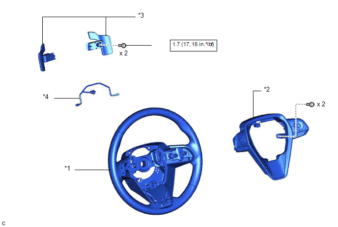
ILLUSTRATION
|
*1 | STEERING WHEEL ASSEMBLY |
*2 | STEERING PAD SWITCH ASSEMBLY |
|
*3 | SHIFT PADDLE SWITCH (TRANSMISSION SHIFT SWITCH ASSEMBLY) |
*4 | NO. 1 SWITCH WIRE |
.png) |
N*m (kgf*cm, ft.*lbf): Specified torque |
● | Non-reusable part |
|
★ | Precoated part |
- | - |
READ NEXT:
 Removal
REMOVAL CAUTION / NOTICE / HINT
The necessary procedures (adjustment, calibration, initialization or registration) that must be performed after parts are removed and installed, or replaced during sh
Inspection
INSPECTION PROCEDURE 1. INSPECT SHIFT PADDLE SWITCH (TRANSMISSION SHIFT SWITCH ASSEMBLY)
(a) Shift Paddle Switch LH (Transmission Shift Switch Assembly):
(1) Measure the resistance according t
Installation
INSTALLATION PROCEDURE 1. INSTALL NO. 1 SWITCH WIRE
HINT: Perform this procedure only when replacement of the No. 1 switch wire is necessary.
(a) Engage the 2 guides to install the No. 1 switch wi
SEE MORE:
Installation
INSTALLATION PROCEDURE 1. INSTALL FLOW SHUTTING VALVE (WATER BY-PASS HOSE ASSEMBLY)
(a) Connect the flow shutting valve (water by-pass hose assembly) to the transmission oil cooler and slide the clip to secure it.
*a 2 to 7 mm (0.0787 to 0.276 in.)
*b Paint Mark
*c 45
Terminals Of Ecu
TERMINALS OF ECU CHECK INSTRUMENT PANEL JUNCTION BLOCK ASSEMBLY AND MAIN BODY ECU (MULTIPLEX NETWORK BODY ECU)
(a) Disconnect the MB main body ECU (multiplex network body ECU) connector.
Click here (b) Measure the voltage and resistance according to the value(s) in the table below.
HINT: Me
© 2023-2026 Copyright www.tocamry.com
