Toyota Camry (XV70): Inspection
INSPECTION
PROCEDURE
1. INSPECT SHIFT PADDLE SWITCH (TRANSMISSION SHIFT SWITCH ASSEMBLY)
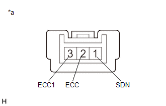
(a) Shift Paddle Switch LH (Transmission Shift Switch Assembly):
| (1) Measure the resistance according to the value(s) in the table below. Standard Resistance:
If the result is not as specified, replace the shift paddle switch LH (transmission shift switch assembly). |
|
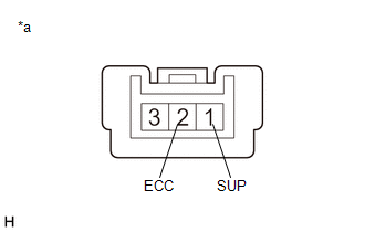
(b) Shift Paddle Switch RH (Transmission Shift Switch Assembly):
| (1) Measure the resistance according to the value(s) in the table below. Standard Resistance:
If the result is not as specified, replace the shift paddle switch RH (transmission shift switch assembly). |
|
READ NEXT:
 Installation
INSTALLATION PROCEDURE 1. INSTALL NO. 1 SWITCH WIRE
HINT: Perform this procedure only when replacement of the No. 1 switch wire is necessary.
(a) Engage the 2 guides to install the No. 1 switch wi
Speed Sensor
ComponentsCOMPONENTS ILLUSTRATION
*1 TRANSMISSION REVOLUTION SENSOR (NC)
*2 TRANSMISSION REVOLUTION SENSOR (NT)
*3 SPACER
- -
Tightening torque for
Torque Converter And Drive Plate
InspectionINSPECTION PROCEDURE
1. INSPECT TORQUE CONVERTER ASSEMBLY (a) Inspect the one-way clutch. Press on the splines of the stator with a finger and rotate it. Check that it rotates smoothly whe
SEE MORE:
Position Initialization Incomplete (B2343)
DESCRIPTION This DTC is stored when the sliding roof ECU (sliding roof drive gear assembly) or roof sunshade ECU (sliding roof drive gear assembly) has not been initialized. Sliding Roof
DTC No. Detection Item
DTC Detection Condition
Trouble Area
B2343 Position Initia
Driving in vehicle-to-vehicle distance control mode - Dynamic radar cruise
control
This mode employs a radar to detect the presence of vehicles up to
approximately 328 ft. (100 m) ahead, determines the current vehicle-to-
vehicle following distance, and operates to maintain a suitable following
distance from the vehicle ahead. The desired vehicle-to-vehicle
distance can also b
