Toyota Camry (XV70): Steering Knuckle
Components
COMPONENTS
ILLUSTRATION
|
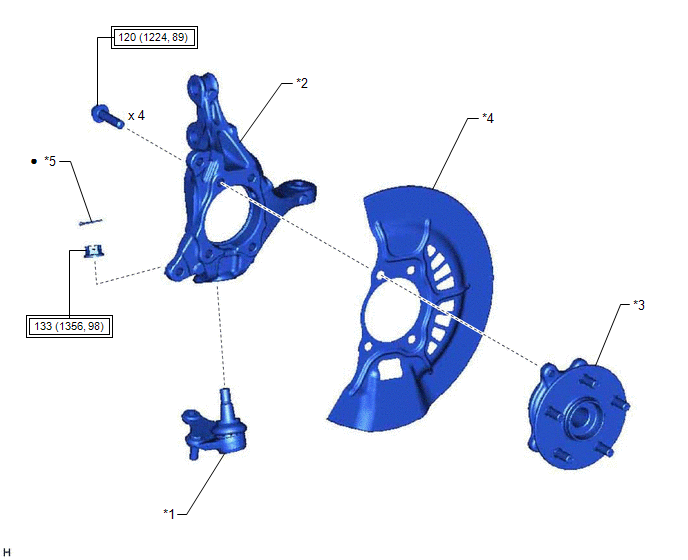
*1 | FRONT LOWER BALL JOINT ASSEMBLY |
*2 | STEERING KNUCKLE |
|
*3 | FRONT AXLE HUB SUB-ASSEMBLY |
*4 | FRONT DISC BRAKE DUST COVER |
|
*5 | COTTER PIN |
- | - |
.png) |
Tightening torque for "Major areas involving basic vehicle performance such as moving/turning/stopping" : N*m (kgf*cm, ft.*lbf) |
● | Non-reusable part |
Removal
REMOVAL
CAUTION / NOTICE / HINT
The necessary procedures (adjustment, calibration, initialization, or registration) that must be performed after parts are removed and installed, or replaced during steering knuckle removal/installation are shown below.
Necessary Procedures After Parts Removed/Installed/Replaced|
Replaced Part or Performed Procedure |
Necessary Procedure | Effect/Inoperative Function when Necessary Procedure not Performed |
Link |
|---|---|---|---|
| Front wheel alignment adjustment |
Perform system variant learning and acceleration sensor zero point calibration. |
| w/ Electric Parking Brake System:
w/o Electric Parking Brake System:
|
HINT:
- Use the same procedure for the RH side and LH side.
- The following procedure is for the LH side.
PROCEDURE
1. REMOVE FRONT AXLE ASSEMBLY
Click here .gif)
2. REMOVE FRONT LOWER BALL JOINT ASSEMBLY
Click here
3. REMOVE STEERING KNUCKLE
| (a) Secure the front axle assembly between aluminum plates in a vise. NOTICE: Do not overtighten the vise. |
|
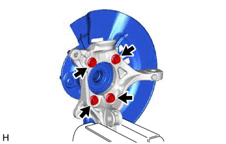
(b) Remove the 4 bolts, front axle hub sub-assembly and front disc brake dust cover from the steering knuckle.
NOTICE:
- Do not drop the front axle hub sub-assembly.
- Be careful not to damage the speed sensor rotor or contact surfaces.
- Do not allow foreign matter to contact the speed sensor rotor or contact surfaces.
Installation
INSTALLATION
CAUTION / NOTICE / HINT
HINT:
- Use the same procedure for the RH side and LH side.
- The following procedure is for the LH side.
PROCEDURE
1. INSTALL STEERING KNUCKLE
(a) Secure the steering knuckle between aluminum plates in a vise.
NOTICE:
Do not overtighten the vise.
(b) Install the front axle hub sub-assembly and front disc brake dust cover to the steering knuckle with the 4 bolts.
Torque:
120 N
READ NEXT:
 Drive Shaft System
PrecautionPRECAUTION
NOTICE OF REMOVING AND INSTALLING FRONT DRIVE SHAFT ASSEMBLY RH (for AWD)
(a) When removing and installing the front drive shaft assembly RH in an AWD vehicle, be sure to firs
SEE MORE:
Evaporative Emission System Leak Detected (Large Leak) (P045500,P045600)
DTC SUMMARY
DTC No. Detection Item
DTC Detection Condition Trouble Area
MIL Memory
Note P045500
Evaporative Emission System Leak Detected (Large Leak)
Leak detection pump creates negative pressure (vacuum) in EVAP system and EVAP system pressure is measured
Removal
REMOVAL PROCEDURE 1. REMOVE LUGGAGE COMPARTMENT DOOR COVER
Click here 2. REMOVE REAR SPOILER
(a) Apply protective tape around the rear spoiler as shown in the illustration.
Protective Tape (b) except TRD:
(1) Remove the 2 bolts.
(2) Separate
