Toyota Camry (XV70): Replacement
REPLACEMENT
CAUTION / NOTICE / HINT
HINT:
- Use the same procedure for bank 1 and bank 2.
- The following procedure is for bank 2.
PROCEDURE
1. REPLACE INTAKE VALVE GUIDE BUSH
(a) Heat the cylinder head LH to between 80 and 100°C (176 and 212°F).
(b) Place the cylinder head LH on wooden blocks.
CAUTION:
Be sure to wear protective gloves.
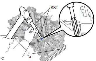
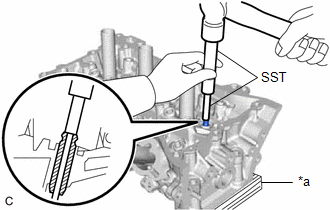
| (c) Using SST and a hammer, tap out the intake valve guide bush. SST: 09201-10000 09201-01050 SST: 09950-70010 09951-07100 |
|
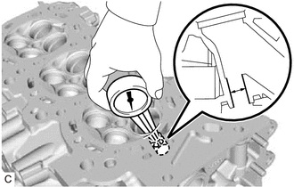
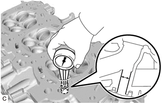
| (d) Using a caliper gauge, measure the intake valve guide bush bore diameter of the cylinder head LH. Standard Intake Valve Guide Bush Bore Diameter: 10.285 to 10.306 mm (0.405 to 0.406 in.) New Guide Bush Selection Chart:
HINT:
|
|
(e) Heat the cylinder head LH to between 80 and 100°C (176 and 212°F).
(f) Place the cylinder head LH on wooden blocks.
CAUTION:
Be sure to wear protective gloves.
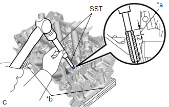
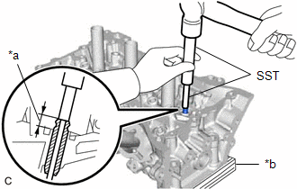
| (g) Using SST and a hammer, tap in a new intake valve guide bush to the specified protrusion height. SST: 09201-10000 09201-01050 SST: 09950-70010 09951-07100 Standard Protrusion Height: 9.30 to 9.70 mm (0.366 to 0.382 in.) |
|
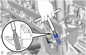
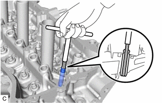
| (h) Using a sharp 5.5 mm reamer, ream the intake valve guide bush to obtain the specified oil clearance. Standard Oil Clearance: 0.025 to 0.060 mm (0.000984 to 0.00236 in.) |
|
2. REPLACE EXHAUST VALVE GUIDE BUSH
(a) Heat the cylinder head LH to between 80 and 100°C (176 and 212°F).
(b) Place the cylinder head LH on wooden blocks.
CAUTION:
Be sure to wear protective gloves.
| (c) Using SST and a hammer, tap out the exhaust valve guide bush. SST: 09201-10000 09201-01050 SST: 09950-70010 09951-07100 |
|
| (d) Using a caliper gauge, measure the exhaust valve guide bush bore diameter of the cylinder head LH. Standard Exhaust Valve Guide Bush Bore Diameter: 10.285 to 10.306 mm (0.405 to 0.406 in.) New Guide Bush Selection Chart:
HINT:
|
|
(e) Heat the cylinder head LH to between 80 and 100°C (176 and 212°F).
(f) Place the cylinder head LH on wooden blocks.
CAUTION:
Be sure to wear protective gloves.
| (g) Using SST and a hammer, tap in a new exhaust valve guide bush to the specified protrusion height. SST: 09201-10000 09201-01050 SST: 09950-70010 09951-07100 Standard Protrusion Height: 9.30 to 9.70 mm (0.366 to 0.382 in.) |
|
| (h) Using a sharp 5.5 mm reamer, ream the exhaust valve guide bush to obtain the specified oil clearance. Standard Oil Clearance: 0.030 to 0.065 mm (0.00118 to 0.00256 in.) |
|
3. REPLACE RING PIN
NOTICE:
It is not necessary to remove the ring pins unless they are being replaced.
(a) Using a plastic hammer, tap in new ring pins to the cylinder head LH and cylinder head sub-assembly.
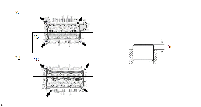
|
*A | for Bank 1 |
*B | for Bank 2 |
|
*C | w/ Ring Pin |
- | - |
|
*a | Protrusion Height |
- | - |
Standard Protrusion Height:
2.5 to 3.5 mm (0.0984 to 0.138 in.)
4. REPLACE STUD BOLT
NOTICE:
If a stud bolt is deformed or its threads are damaged, replace it.
(a) Using E6 and E8 "TORX" socket wrenches, install the stud bolts to the cylinder head LH.
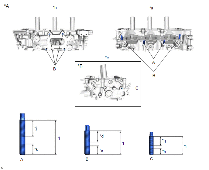
|
*A | for Bank 2 |
*B | w/ Stud Bolt |
|
*a | Intake Side |
*b | Exhaust Side |
|
*c | Rear Side |
*d | 20 mm (0.787 in.) |
|
*e | 13 mm (0.512 in.) |
*f | 35 mm (1.38 in.) |
|
*g | 16 mm (0.630 in.) |
*h | 9 mm (0.354 in.) |
|
*i | 27 mm (1.06 in.) |
*j | 26 mm (1.02 in.) |
|
*k | 16.7 mm (0.657 in.) |
*l | 51.7 mm (2.04 in.) |
Torque:
Bolt (A), (B) :
10 N·m {102 kgf·cm, 7 ft·lbf}
Bolt (C) :
4.0 N·m {41 kgf·cm, 35 in·lbf}
(b) Using E6 and E8 "TORX" socket wrenches, install the stud bolts to the cylinder head sub-assembly.
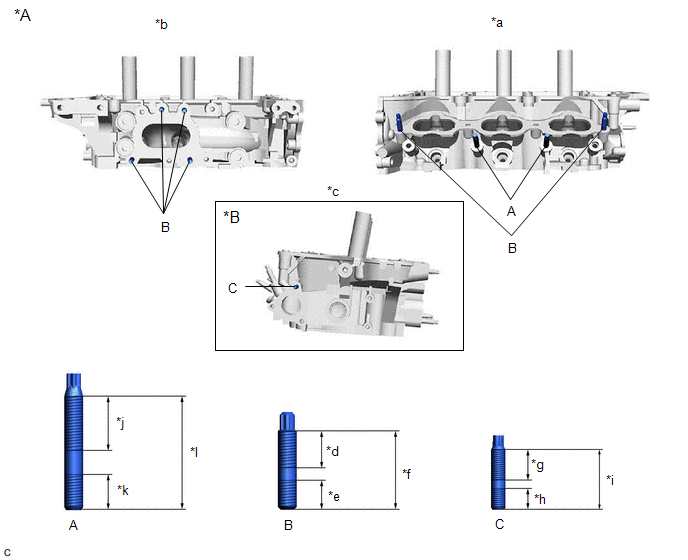
|
*A | for Bank 1 |
*B | w/ Stud Bolt |
|
*a | Intake Side |
*b | Exhaust Side |
|
*c | Rear Side |
*d | 20 mm (0.787 in.) |
|
*e | 13 mm (0.512 in.) |
*f | 35 mm (1.38 in.) |
|
*g | 16 mm (0.630 in.) |
*h | 9 mm (0.354 in.) |
|
*i | 27 mm (1.06 in.) |
*j | 26 mm (1.02 in.) |
|
*k | 16.7 mm (0.657 in.) |
*l | 51.7 mm (2.04 in.) |
Torque:
Bolt (A), (B) :
10 N·m {102 kgf·cm, 7 ft·lbf}
Bolt (C) :
4.0 N·m {41 kgf·cm, 35 in·lbf}
5. REPLACE STRAIGHT PIN
NOTICE:
If a straight pin is deformed, replace it.
(a) Using a plastic hammer, tap in new straight pins to the cylinder head LH as shown in the illustration.
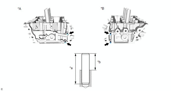
|
*A | for Bank 1 |
*B | for Bank 2 |
|
*a | 34 mm (1.34 in.) |
*b | Protrusion Height |
Standard Protrusion Height:
17.5 to 19.5 mm (0.689 to 0.768 in.)
READ NEXT:
 Reassembly
REASSEMBLY CAUTION / NOTICE / HINT
HINT:
Use the same procedure for bank 1 and bank 2.
The following procedure is for bank 2.
PROCEDURE 1. INSTALL SPARK PLUG TUBE HINT:
When using a ne
Repair
REPAIR CAUTION / NOTICE / HINT
HINT:
Use the same procedure for bank 1 and bank 2.
The following procedure is for bank 2.
PROCEDURE 1. REPAIR INTAKE VALVE SEAT
NOTICE:
Repair the i
SEE MORE:
Registration
REGISTRATION PROCEDURE 1. BEFORE REGISTRATION
NOTICE:
The transmitter ID is written on the tire pressure warning valve and transmitter. It is not possible to read the transmitter ID after installing the tire onto the wheel. Therefore, make a note of the transmitter ID before installing the tir
Initialization
INITIALIZATION
NOTICE:
Initialization can be confirmed through the tire pressure warning light.
If the ignition switch is turned off during initialization, the tire pressure warning ECU and receiver memorizes that initialization was being performed. Therefore, it is not necessary to perfo
