Toyota Camry (XV70): System Diagram
Toyota Camry Repair Manual XV70 (2018-2024) / Engine, Hybrid System / 2gr-fks (cooling) / Cooling Fan System / System Diagram
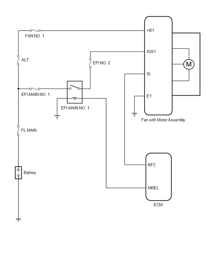
SYSTEM DIAGRAM
READ NEXT:
 Problem Symptoms Table
PROBLEM SYMPTOMS TABLE
HINT:
Use the table below to help determine the cause of problem symptoms. If multiple suspected areas are listed, the potential causes of the symptoms are listed in order
On-vehicle Inspection
ON-VEHICLE INSPECTION PROCEDURE
1. INSPECT COOLING FAN SYSTEM CAUTION: To prevent injury due to contact with an operating cooling fan, keep your hands and clothing away from the cooling fan when ins
Cooling Fan Circuit
DESCRIPTION The ECM calculates an appropriate cooling fan speed based on the engine coolant temperature, air conditioning switch status, refrigerant pressure, engine speed and vehicle speed, and sends
SEE MORE:
Replacement
REPLACEMENT CAUTION / NOTICE / HINT
HINT:
Use the same procedure for bank 1 and bank 2.
The following procedure is for bank 2.
PROCEDURE 1. REPLACE INTAKE VALVE GUIDE BUSH
(a) Heat the cylinder head LH to between 80 and 100°C (176 and 212°F).
(b) Place the cylinder head LH on woo
On-vehicle Inspection
ON-VEHICLE INSPECTION CAUTION / NOTICE / HINT
NOTICE:
Do not remove the generator pulley cap.
If the generator pulley cap is removed, replace the generator pulley cap and generator pulley with clutch with new ones as the correct grease amount cannot be confirmed.
HINT: If it is confir
© 2023-2026 Copyright www.tocamry.com
