Toyota Camry (XV70): Telephone And Gps Antenna Cords (for Front Side)
Components
COMPONENTS
ILLUSTRATION
|
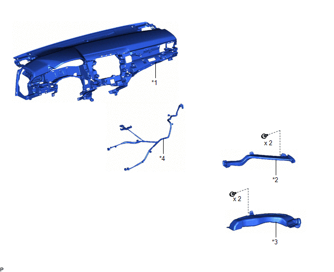
*1 | INSTRUMENT PANEL SAFETY PAD SUB-ASSEMBLY |
*2 | NO. 2 SIDE DEFROSTER NOZZLE DUCT |
|
*3 | NO. 3 HEATER TO REGISTER DUCT SUB-ASSEMBLY |
*4 | TELEPHONE AND GPS ANTENNA CORD |
Removal
REMOVAL
CAUTION / NOTICE / HINT
The necessary procedures (adjustment, calibration, initialization, or registration) that must be performed after parts are removed and installed, or replaced during telephone and GPS antenna cord removal/installation are shown below.
Necessary Procedures After Parts Removed/Installed/Replaced|
Replaced Part or Performed Procedure |
Necessary Procedure | Effect/Inoperative Function when Necessary Procedure not Performed |
Link |
|---|---|---|---|
|
Disconnect cable from negative battery terminal |
Perform steering sensor zero point calibration. |
Lane Tracing Assist System |
|
|
Pre-collision System | |||
|
Memorize steering angle neutral point |
Parking Assist Monitor System |
| |
|
Panoramic View Monitor System |
|
CAUTION:
Some of these service operations affect the SRS airbag system. Read the precautionary notices concerning the SRS airbag system before servicing.
.png)
Click here
.gif)
PROCEDURE
1. REMOVE INSTRUMENT PANEL SAFETY PAD SUB-ASSEMBLY
Click here
2. REMOVE NO. 2 SIDE DEFROSTER NOZZLE DUCT
Click here
3. REMOVE NO. 3 HEATER TO REGISTER DUCT SUB-ASSEMBLY
Click here
4. REMOVE TELEPHONE AND GPS ANTENNA CORD
(a) Disconnect the connector.
.png)
(b) Disengage the 2 claws.
(c) Disengage the 7 clamps to remove the telephone and GPS antenna cord.
Installation
INSTALLATION
PROCEDURE
1. INSTALL TELEPHONE AND GPS ANTENNA CORD
(a) Engage the 7 clamps.
(b) Engage the 2 claws.
(c) Connect the connector to install the telephone and GPS antenna cord.
2. INSTALL NO. 3 HEATER TO REGISTER DUCT SUB-ASSEMBLY
Click here
.gif)
3. INSTALL NO. 2 SIDE DEFROSTER NOZZLE DUCT
Click here
4. INSTALL INSTRUMENT PANEL SAFETY PAD SUB-ASSEMBLY
Click here
READ NEXT:
 Telephone And Gps Antenna Cords (for Roof Side)
ComponentsCOMPONENTS ILLUSTRATION
*1 TELEPHONE AND GPS ANTENNA CORD
- - RemovalREMOVAL CAUTION / NOTICE / HINT
The necessary procedures (adjustment, calibration, initializatio
Precaution
PRECAUTION PRECAUTION FOR DISCONNECTING CABLE FROM NEGATIVE BATTERY TERMINAL
NOTICE: When disconnecting the cable from the negative (-) battery terminal, initialize the following systems after the t
SEE MORE:
Acn Call End
ACN CALL END ACN CALL END This function terminates the ACN (Automatic Collision Notification) to the telematics provider. After a collision in which the DCM receives "Collision Detection Signal", the vehicle will send the emergency call notification to the telematics provider until the emergency cal
Components
COMPONENTS ILLUSTRATION
*1 ENGINE OIL LEVEL SENSOR
*2 NO. 2 OIL PAN SUB-ASSEMBLY
*3 OIL STRAINER SUB-ASSEMBLY
*4 OIL STRAINER GASKET
N*m (kgf*cm, ft.*lbf): Specified torque
● Non-reusable part
