Toyota Camry (XV70): Terminals Of Ecm
TERMINALS OF ECM
HINT:
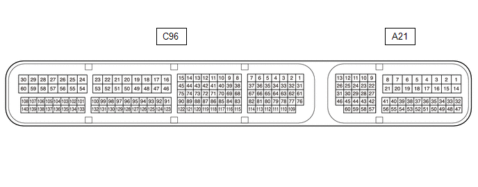
The standard normal voltage and resistance between each pair of ECM terminals is shown in the table below. The appropriate conditions for checking each pair of terminals are also indicated. The result of checks should be compared with the standard normal voltage and resistance for that pair of terminals, displayed in the Specified Condition column. The illustration above can be used as a reference to identify the ECM terminal locations.
|
Terminal No. (Symbol) | Wiring Color |
Terminal Description | Condition |
Specified Condition |
|---|---|---|---|---|
|
C96-53 (E1) - Body ground |
W-B - Body ground | Ground |
Always | Below 1 Ω |
|
A21-1 (BATT) - C96-53 (E1) |
R - W-B | Battery (for measuring battery voltage and for ECM memory) |
Always | 11 to 14 V |
|
C96-135 (LIN) - Body ground |
B - Body ground | LIN communication line |
Engine switch off (while LIN communication stopped) |
10 kΩ or higher |
READ NEXT:
 Diagnosis System
DIAGNOSIS SYSTEM DLC3 (Data Link Connector 3)
(a) Check the DLC3. Click here
BATTERY VOLTAGE Standard Voltage: 11 to 14 V If the voltage is below 11 V, replace or recharge the battery.
Dtc Check / Clear
DTC CHECK / CLEAR CHECK DTC (a) Connect the Techstream to the DLC3.
(b) Turn the engine switch on (IG). (c) Turn the Techstream on.
(d) Enter the following menus: Powertrain / Engine / Trouble Cod
Freeze Frame Data
FREEZE FRAME DATA DESCRIPTION The ECM records vehicle and driving condition information as freeze frame data the moment a DTC is stored. When troubleshooting, freeze frame data can be helpful in deter
SEE MORE:
Adjustment
ADJUSTMENT CAUTION / NOTICE / HINT
*a Centering Bolt
*b Standard Bolt
HINT:
Use the same procedure for the RH side and LH side.
The following procedure is for the LH side.
Centering bolts are used to install the door hinges to the vehicle body and doo
How To Proceed With Troubleshooting
CAUTION / NOTICE / HINT HINT: *: Use the Techstream. PROCEDURE
1.
VEHICLE BROUGHT TO WORKSHOP
NEXT
2.
CUSTOMER PROBLEM ANALYSIS
HINT:
In troubleshooting, confirm that the problem symptoms have been accurately identified. Preconceptions
