Toyota Camry (XV70): Terminals Of Ecu
TERMINALS OF ECU
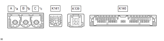
DCM (TELEMATICS TRANSCEIVER)
|
*a | to Telephone Antenna (Sub) |
*b | to GPS Antenna |
|
*c | to Telephone Antenna (Main) |
- | - |
|
Terminal No. (Symbol) | Wiring Color |
Terminal Description | Condition |
Specified Condition |
|---|---|---|---|---|
|
K141-1 (USB-) | - |
USB communication line |
- | - |
|
K141-2 (USB+) | - |
USB communication line |
- | - |
|
K141-3 (USBS) - Body ground |
Shielded - Body ground |
Shield ground | Always |
Below 1 V |
|
K140-31 (USBG) - Body ground |
GR - Body ground | DCM (Telematics Transceiver) power supply ground signal |
Always | Below 1 V |
|
K140-17 (VOT+) - K140-20 (E) |
R - W-B | Sent voice signal |
Calling while using the operator service |
A waveform synchronized with the voice signals received voice is output |
|
K140-15 (USBV) - K140-20 (E) |
L - W-B | DCM (Telematics Transceiver) power supply signal |
Ignition switch off | Below 1 V |
|
Ignition switch to ON |
4.5 to 5.25 V | |||
|
K140-33 (VOT-) - K140-20 (E) |
G - W-B | Sent voice signal |
Calling while using the operator service |
A waveform synchronized with the received voice is output |
|
K140-34 (VOR-) - K140-20 (E) |
W - W-B | Receive voice signal |
Receiving a call while using the operator service |
A waveform synchronized with the sent voice is output |
|
K140-18 (VOR+) - K140-20 (E) |
B - W-B | Receive voice signal |
Receiving a call while using the operator service |
A waveform synchronized with the sent voice is output |
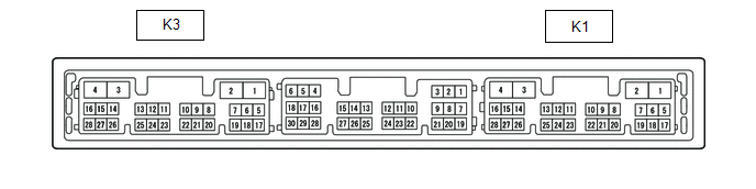
RADIO AND DISPLAY RECEIVER ASSEMBLY
|
Terminal No. (Symbol) | Wiring Color |
Terminal Description | Condition |
Specified Condition |
|---|---|---|---|---|
|
K1-15 (VOT+) - K3-1 (GND1) |
B - BR | Sent voice signal |
Destination assist service in use and vehicle occupant speaking to operator |
A waveform synchronized with the sent voice is output |
|
K1-10 (USBV) - K3-1 (GND1) |
L - BR | DCM (Telematics transceiver) power supply |
Ignition switch to ON |
4.75 to 5.25 V |
|
Ignition switch off | A waveform synchronized with sound is output | |||
|
K1-11 (USBG) - K3-1 (GND1) |
GR - BR | DCM (Telematics Transceiver) power supply ground signal |
Always | Below 1 V |
|
K1-13 (VOR+) - K3-1 (GND1) |
R - BR | Receive voice signal |
Destination assist service in use and operator speaking to vehicle occupant |
A waveform synchronized with the received voice is output |
|
K1-14 (VOR-) - K3-1 (GND1) |
G - BR | Receive voice signal |
Destination assist service in use and operator speaking to vehicle occupant |
A waveform synchronized with the received voice is output |
|
K1-15 (VOT+) - K3-1 (GND1) |
B - BR | Sent voice signal |
Destination assist service in use and operator speaking to vehicle occupant |
A waveform synchronized with the voice signals received voice is output |
|
K1-16 (VOT-) - K3-1 (GND1) |
W - BR | Sent voice signal |
Destination assist service in use and vehicle occupant speaking to operator |
A waveform synchronized with the sent voice is output |
NAVIGATION ECU (w/ Navigation System)

|
Terminal No. (Symbol) | Wiring Color |
Terminal Description | Condition |
Specified Condition |
|---|---|---|---|---|
|
K137-2 (USB4-) | - |
USB communication line |
- | - |
|
K137-1 (USB4+) | - |
USB communication line |
- | - |
|
K137-3 (UGD4) - Body ground |
Shielded - Body ground |
Shield ground | Always |
Below 1 V |
READ NEXT:
 GPS Mark is not Displayed
CAUTION / NOTICE / HINT
NOTICE:
Depending on the parts that are replaced during vehicle inspection or maintenance, performing initialization, registration or calibration may be needed. Refer to
Confirm Cellular Phone Functionality
PROCEDURE
1. CHECK CUSTOMER'S CELLULAR PHONE COMPATIBILITY
(a) Check if the cellular phone is compatible (Refer to http://www.toyota.com/Entune/).
Result Proceed to
Cel
Confirm Vehicle Headunit Functionality
PROCEDURE
1. CHECK CUSTOMER'S CELLULAR PHONE COMPATIBILITY
(a) Check if the cellular phone is compatible (Refer to http://www.toyota.com/Entune/).
Result Proceed to
Cel
SEE MORE:
Portable Player cannot be Registered
CAUTION / NOTICE / HINT HINT: Some versions of "Bluetooth" compatible audio players may not function properly, or the functions may be limited using the radio and display receiver assembly, even if the portable audio player itself can play files.
Click here
PROCEDURE
1.
CHECK
Components
COMPONENTS ILLUSTRATION
*1 FUEL PUMP ASSEMBLY
*2 FUEL PUMP PROTECTOR
*3 NO. 1 FUEL PIPE SUB-ASSEMBLY
*4 NO. 2 FUEL TUBE SUB-ASSEMBLY
*5 FUEL PUMP LIFTER ASSEMBLY
*6 FUEL PUMP LIFTER GUIDE
*7 FUEL PUMP SPACER GASKET
*8 FUEL TUB
