
Toyota Camry (XV70): Terminals Of Ecu
TERMINALS OF ECU
CHECK AIR CONDITIONING AMPLIFIER ASSEMBLY
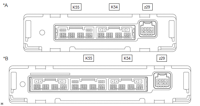
|
*A | w/o Seat Heater |
*B | w/ Seat Heater |
HINT:
- Check from the rear of the connector while it is connected to the air conditioning amplifier assembly.
- Make sure to wait at least 2 minutes after turning the ignition switch off before performing an ECU terminal inspection.
|
Terminal No. (Symbol) |
Wiring Color | Terminal Description |
Condition | Specified Condition |
|---|---|---|---|---|
|
K55-2 (SG-2) - Body ground |
W - Body ground | Ground for thermistor assembly |
Always | Below 1 V |
|
K55-3 (SG-4) - Body ground |
L - Body ground | Ground for air conditioner pressure sensor |
Always | Below 1 V |
|
K55-6 (S5-3) - K55-3 (SG-4) |
GR - L | Power supply for air conditioner pressure sensor |
Ignition switch ON | 4.75 to 5.25 V |
|
Ignition switch off | Below 1 V | |||
|
K55-13 (TAM) - K55-2 (SG-2) |
R - W | Thermistor assembly signal |
| 1.05 to 1.45 V |
| 0.64 to 0.87 V | |||
|
K55-24 (PRE) - K55-3 (SG-4) |
W - L | Air conditioner pressure sensor signal |
| 4.61 V or higher |
| Below 0.74 V | |||
| 0.74 to 4.61 V | |||
|
K54-1 (B) - K54-4 (GND) |
LA-B - W-B | Power source (Back-up) |
Always | 11 to 14 V |
|
K54-2 (IG+) - K54-4 (GND) |
LA-GR - W-B | Power source (IG) |
Ignition switch ON | 11 to 14 V |
|
Ignition switch off | Below 1 V | |||
|
K54-3 (SOL+) - K54-4 (GND) |
R - W-B | Compressor solenoid operation signal |
| Pulse generation (See waveform 1) |
|
K54-4 (GND) - Body ground |
W-B - Body ground | Ground for main power supply |
Always | Below 1 V |
|
K54-6 (BLW) - K54-4 (GND) |
LG - W-B | Blower motor speed control signal |
| Pulse generation (See waveform 2) |
|
K54-11 (CANH) - K54-12 (CANL) |
SB - W | CAN communication system |
CAN communication is performed |
Pulse generation |
|
K54-14 (LIN1) - K54-4 (GND) |
W - W-B | LIN communication signal |
Ignition switch ON | Pulse generation (See waveform 3) |
|
z29-2 (1A) - Body ground |
- | Ground for BUS IC |
Always | Below 1 V |
|
z29-3 (2A) - z29-2 (1A) |
- | BUS IC control signal |
Ignition switch ON | Pulse generation (See waveform 4) |
|
z29-4 (3A) - z29-2 (1A) |
- | Power supply for BUS IC |
Ignition switch off | 11 to 14 V |
|
z29-5 (4A) - Body ground |
GR - Body ground | Ground for No. 1 cooler thermistor |
Always | Below 1 V |
|
z29-6 (5A) - z29-5 (4A) |
GR - GR | No. 1 cooler thermistor signal |
| 1.7 to 2.1 V |
| 0.9 to 1.3 V |
(a) Waveform 1:
.png)
|
Item | Content |
|---|---|
|
Terminal No. | K54-3 (SOL+) - K54-4 (GND) |
|
Tool Setting | 5 V/DIV., 500 ?s./DIV. |
|
Condition |
|
(b) Waveform 2:
.png)
|
Item | Content |
|---|---|
|
Terminal No. | K54-6 (BLW) - K54-4 (GND) |
|
Tool Setting | 2 V/DIV., 1 ms./DIV. |
|
Condition |
|
(c) Waveform 3:
.png)
|
Item | Content |
|---|---|
|
Terminal No. | K54-14 (LIN1) - K54-4 (GND) |
|
Tool Setting | 2 V/DIV., 20 ms./DIV. |
|
Condition | Ignition switch ON |
(d) Waveform 4:
.png)
|
Item | Content |
|---|---|
|
Terminal No. | z29-3 (2A) - z29-2 (1A) |
|
Tool Setting | 2 V/DIV., 2 ms./DIV. |
|
Condition | Ignition switch ON |
CHECK AIR CONDITIONING CONTROL ASSEMBLY
.png)
HINT:
Check from the rear of the connector while it is connected to the air conditioning control assembly.
|
Terminal No. (Symbol) |
Wiring Color | Terminal Description |
Condition | Specified Condition |
|---|---|---|---|---|
|
K26-2 (IG+) - K26-6 (GND) |
GR - W-B | Power source (IG) |
Ignition switch off | Below 1 V |
|
Ignition switch ON | 11 to 14 V | |||
|
K26-6 (GND) - Body ground |
W-B - Body ground | Ground for air conditioning control assembly |
Always | Below 1 V |
|
K26-9 (LIN1) - Body ground |
LG - Body ground | LIN communication signal |
Ignition switch ON | Pulse generation (See waveform) |
|
K26-11 (ILL+) - Body ground |
W - Body ground |
Illumination signal | Light control switch in off position |
Below 1 V |
| Light control switch in tail or head position |
11 to 14 V | |||
|
K26-15 (ILL-) - Body ground |
B - Body ground | Illumination signal |
Always | Below 1 V |
(a) Waveform:
|
Item | Content |
|---|---|
|
Terminal No. | K26-9 (LIN1) - Body ground |
|
Tool Setting | 2 V/DIV., 20 ms./DIV. |
|
Condition | Ignition switch ON |
READ NEXT:
 Diagnosis System
DIAGNOSIS SYSTEM DESCRIPTION Air conditioning system data and Diagnostic Trouble Codes (DTCs) can be read through the Data Link Connector 3 (DLC3) of the vehicle. When the system seems to be malfuncti
Dtc Check / Clear
DTC CHECK / CLEAR DTC CHECK USING TECHSTREAM (a) Connect the Techstream to the DLC3.
(b) Turn the ignition switch to ON. (c) Turn the Techstream on.
(d) Enter the following menus: Body Electrical /
Data List / Active Test
DATA LIST / ACTIVE TEST DATA LIST NOTICE:
In the table below, the values listed under "Normal Condition" are reference values. Do not depend solely on these reference values when deciding whether a p
SEE MORE:
Sudden start restraint control (Drive-Start Control [DSC] )
When the following unusual operation is performed with the accelerator
pedal depressed, the engine output may be restrained.
When the shift lever is shifted to R*.
When the shift lever is shifted from P or R to forward drive shift
position such as D*.
When the system operates, a message
Insufficient Coolant Temperature for Closed Loop Fuel Control (P012500)
DESCRIPTION Refer to DTC P011511. Click here
DTC No. Detection Item
DTC Detection Condition Trouble Area
MIL Memory
Note P012500
Insufficient Coolant Temperature for Closed Loop Fuel Control
The engine coolant temperature does not reach the closed loop
