
Toyota Camry (XV70): Terminals Of Ecu
TERMINALS OF ECU
CHECK MAIN BODY ECU (MULTIPLEX NETWORK BODY ECU) AND INSTRUMENT PANEL JUNCTION BLOCK ASSEMBLY
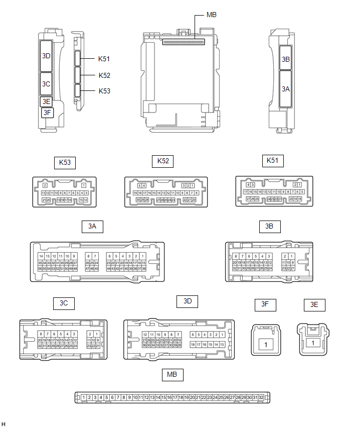
(a) Disconnect the instrument panel junction block assembly and main body ECU (multiplex network body ECU) connectors.
(b) Measure the voltage and resistance according to the value(s) in the table below.
|
Terminal No. (Symbol) | Wiring Color |
Terminal Description | Condition |
Specified Condition |
|---|---|---|---|---|
|
3B-3 - Body ground | W-B - Body ground |
Ground | Always |
Below 1 ? |
|
3C-1 - Body ground | LG - Body ground |
Battery power supply | Always |
11 to 14 V |
|
3F-1 - Body ground | W - Body ground |
Battery power supply | Always |
11 to 14 V |
|
K51-19 (GND2) - Body ground |
W-B - Body ground | Ground |
Always | Below 1 ? |
(c) Connect the instrument panel junction block assembly and main body ECU (multiplex network body ECU) connectors.
(d) Measure the voltage and check for pulses according to the value(s) in the table below.
|
Terminal No. (Symbol) | Wiring Color |
Terminal Description | Condition |
Specified Condition |
|---|---|---|---|---|
|
3A-17 - Body ground |
R - Body ground*1 LA-R - Body ground*2 |
IG power supply | Ignition switch ON |
11 to 14 V |
| Ignition switch off |
Below 1 V | |||
|
3A-30 - Body ground |
LG - Body ground |
ACC power supply | Ignition switch ACC |
11 to 14 V |
| Ignition switch off |
Below 1 V | |||
|
3A-31 - Body ground |
V - Body ground |
Rear door courtesy light switch assembly RH input |
Rear door RH open | Below 1 V |
|
Rear door RH closed | 11 to 14 V | |||
|
3A-36 - Body ground*3 |
W - Body ground |
Footwell light LH (No. 1 interior illumination light assembly) drive output |
Footwell light LH (No. 1 interior illumination light assembly) off |
11 to 14 V |
| Footwell light LH (No. 1 interior illumination light assembly) dimmer control operating (dimming) |
Pulse generation | |||
|
Footwell light LH (No. 1 interior illumination light assembly) at full brightness |
Below 2.2 V | |||
|
3A-37 - Body ground*3 |
B - Body ground |
Footwell light RH (No. 1 interior illumination light assembly) drive output |
Footwell light RH (No. 1 interior illumination light assembly) off |
11 to 14 V |
| Footwell light RH (No. 1 interior illumination light assembly) dimmer control operating (dimming) |
Pulse generation | |||
|
Footwell light RH (No. 1 interior illumination light assembly) at full brightness |
Below 2.2 V | |||
|
3B-10 - Body ground |
B - Body ground |
Map light (roof console box sub-assembly), room light assembly*4, spot light assembly*5 and vanity light assembly LH and RH*6 power supply |
DOME CUT relay on | 11 to 14 V |
|
DOME CUT relay off | Below 1 V | |||
|
3B-12 - Body ground |
GR - Body ground |
Front door unlock detection switch RH input |
Front door RH locked |
11 to 14 V |
| Front door RH unlocked |
Below 1 V | |||
|
3B-13 - Body ground |
W - Body ground |
Front door unlock detection switch LH input |
Front door LH locked |
11 to 14 V |
| Front door LH unlocked |
Below 1 V | |||
|
3B-14 - Body ground |
GR - Body ground |
Rear door unlock detection switch LH input |
Rear door LH locked | 11 to 14 V |
|
Rear door LH unlocked |
Below 1 V | |||
|
3B-24 - Body ground*2 |
LA-LG - Body ground | Ignition key cylinder light (transponder key coil) power supply |
Always | 11 to 14 V |
|
3B-24 - Body ground*7 |
LG - Body ground | Instrument panel ambient illumination light (instrument panel light assembly) power supply |
Always | 11 to 14 V |
|
3B-25 - Body ground*3 |
BE - Body ground | Footwell light RH (No. 1 interior illumination light assembly) power supply |
Always | 11 to 14 V |
|
3B-26 - Body ground*8 |
R - Body ground | Inside handle illumination light (No. 1 interior illumination light assembly) power supply |
Always | 11 to 14 V |
|
3B-27 - Body ground*3 |
B - Body ground | Footwell light LH (No. 1 interior illumination light assembly) power supply |
Always | 11 to 14 V |
|
3B-29 - Body ground |
LA-G - Body ground | Illuminated entry system drive output |
Map light LH and map light RH (map light (roof console box sub-assembly))*5, room light assembly*4 and ignition key cylinder light (transponder key coil)*2 off (when operated by illuminated entry system) |
11 to 14 V |
| Map light LH and map light RH (map light (roof console box sub-assembly))*5, room light assembly*4 and ignition key cylinder light (transponder key coil)*2 on (when operated by illuminated entry system) |
Below 1 V | |||
|
3D-19 - Body ground |
LA-B - Body ground |
No. 1 luggage compartment light assembly and courtesy light assembly LH and RH power supply |
DOME CUT relay on | 11 to 14 V |
|
DOME CUT relay off | Below 1 V | |||
|
3D-24 - Body ground |
G - Body ground | Rear door courtesy light switch assembly LH input |
Rear door LH open | Below 1 V |
|
Rear door LH closed | 11 to 14 V | |||
|
3D-34 - Body ground |
LA-GR - Body ground |
Luggage compartment door courtesy light switch (luggage compartment door lock assembly) input |
Luggage compartment door open |
Below 1 V |
| Luggage compartment door closed |
11 to 14 V | |||
|
K51-20 (LSWR) - Body ground |
L - Body ground |
Rear door unlock detection switch RH input |
Rear door RH locked | 11 to 14 V |
|
Rear door RH unlocked |
Below 1 V | |||
|
K52-1 (FLCY) - Body ground |
W - Body ground | Front door courtesy light switch assembly LH input |
Front door LH open | Below 1 V |
|
Front door LH closed |
11 to 14 V | |||
|
K52-2 (FLCL) - Body ground*9 |
G - Body ground |
Courtesy light assembly LH drive output |
Courtesy light assembly LH off |
11 to 14 V |
| Courtesy light assembly LH on |
Below 1 V | |||
|
K52-3 (FRCL) - Body ground*9 |
L - Body ground |
Courtesy light assembly RH drive output |
Courtesy light assembly RH off |
11 to 14 V |
| Courtesy light assembly RH on |
Below 1 V | |||
|
K52-6 (FRCY) - Body ground |
BE - Body ground |
Front door courtesy light switch assembly RH input |
Front door RH open | Below 1 V |
|
Front door RH closed |
11 to 14 V | |||
|
K52-20 (TCYL) - Body ground |
GR - Body ground |
No. 1 luggage compartment light assembly drive output |
No. 1 luggage compartment light assembly off |
11 to 14 V |
| No. 1 luggage compartment light assembly on |
Below 1 V | |||
|
K53-20 (LED1) - Body ground*7 |
W - Body ground |
Instrument panel ambient illumination light (instrument panel light assembly) drive output |
Instrument panel ambient illumination light (instrument panel light assembly) off |
11 to 14 V |
| Instrument panel ambient illumination light (instrument panel light assembly) dimmer control operating (dimming) |
Pulse generation | |||
|
Instrument panel ambient illumination light (instrument panel light assembly) at full brightness |
Below 2.2 V | |||
|
K53-21 (LED2) - Body ground*8 |
R - Body ground |
Inside handle illumination light (No. 1 interior illumination light assembly) drive output |
Inside handle illumination light (No. 1 interior illumination light assembly) off |
11 to 14 V |
| Inside handle illumination light (No. 1 interior illumination light assembly) dimmer control operating (dimming) |
Pulse generation | |||
|
Inside handle illumination light (No. 1 interior illumination light assembly) at full brightness |
Below 2.2 V |
- *1: w/ Smart Key System
- *2: w/o Smart Key System
- *3: w/ Footwell Light
- *4: w/ Room Light (for Bulb Type)
- *5: w/ Room Light (for LED Type)
- *6: w/ Vanity Light
- *7: w/ Instrument Panel Ambient Illumination Light
- *8: w/ Inside Handle Illumination Light
- *9: w/ Courtesy Light
CHECK CERTIFICATION ECU (SMART KEY ECU ASSEMBLY) (w/ Smart Key System)
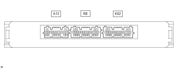
(a) Measure the voltage according to the value(s) in the table below.
|
Terminal No. (Symbol) | Wiring Color |
Terminal Description | Condition |
Specified Condition |
|---|---|---|---|---|
|
K62-10 (SWIL) - K62-11 (AGND) |
W - BE | Engine switch illumination drive output |
Engine switch illumination on |
11 to 14 V |
| Engine switch illumination off |
Below 1 V |
READ NEXT:
SEE MORE:
 Terminals Of Ecu
TERMINALS OF ECU TERMINALS OF ECU
*a Component without harness connected
(Skid Control ECU (Brake Actuator Assembly))
- -
HINT:
As a waterproof connector is used for the brake actuator assembly, voltage and waveform inspections cannot be performed with the connector c
Parts Location
PARTS LOCATION ILLUSTRATION
*1 FRONT AXLE HUB SUB-ASSEMBLY RH
- FRONT SPEED SENSOR ROTOR RH
*2 FRONT SPEED SENSOR RH
*3 FRONT AXLE HUB SUB-ASSEMBLY LH
- FRONT SPEED SENSOR ROTOR LH
*4 FRONT SPEED SENSOR LH
*5 REAR AXLE HUB AND BEARING ASSEMBLY R
