Toyota Camry (XV70): Terminals Of Ecu
TERMINALS OF ECU
TERMINALS OF ECU

|
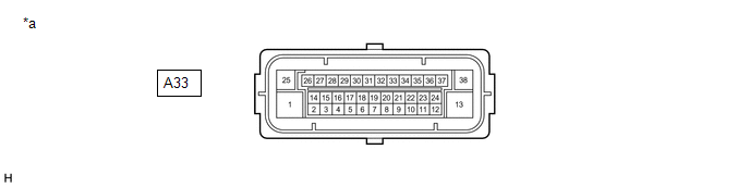
*a | Component without harness connected (Skid Control ECU (Brake Actuator Assembly)) |
- | - |
HINT:
- As a waterproof connector is used for the brake actuator assembly, voltage and waveform inspections cannot be performed with the connector connected.
- Use the Techstream to read data and perform Active Tests when inspecting the operation and communication status of the brake actuator assembly.
Click here
.gif)
|
Terminal No. (Symbol) | Terminal Description |
|---|---|
|
1 (+BM) | ABS motor relay power supply |
|
2 (SP1) | Speed signal output |
|
3 (STPO) | Stop light control relay (stop light switch assembly) output |
|
4 (FR-) | Front wheel speed RH (-) signal input |
|
5 | - |
|
6 | - |
|
7 | - |
|
8 (FL-) | Front wheel speed LH (-) signal input |
|
9 (STP) | Stop light switch assembly signal input |
|
10 | - |
|
11 | - |
|
12 | - |
|
13 (GND2) | Pump motor ground |
|
14 (CANL) | CAN communication line L |
|
15 | - |
|
16 (FR+) | Front wheel speed RH (+) power supply output |
|
17 (RR+) | Rear wheel speed RH (+) power supply output |
|
18 (RL-) | Rear wheel speed LH (-) signal input |
|
19 (FL+) | Front wheel speed LH (+) power supply output |
|
20 | - |
|
21 | - |
|
22 (CSW) | VSC OFF switch input |
|
23 | - |
|
24 (STP2) | Stop light signal input |
|
25 (+BS) | ABS solenoid relay power supply |
|
26 (CANH) | CAN communication line H |
|
27 | - |
|
28 (IG1) | IG1 power source input |
|
29 (RR-) | Rear wheel speed RH (-) signal input |
|
30 | - |
|
31 (RL+) | Rear wheel speed LH (+) power supply output |
|
32 | - |
|
33 | - |
|
34 | - |
|
35 | - |
|
36 | - |
|
37 | - |
|
38 (GND1) | Skid control ECU (brake actuator assembly) ground |
TERMINAL INSPECTION
(a) Disconnect the A33 skid control ECU (brake actuator assembly) connector and measure the voltage and resistance on the wire harness side.
|
*a | Front view of wire harness connector (to Skid Control ECU (Brake Actuator Assembly)) |
- | - |
(b) Measure the voltage or resistance according to the value(s) in the table below.
Standard|
Terminal No. (Symbol) | Wiring Color |
Terminal Description | Condition |
Specified Condition |
|---|---|---|---|---|
|
A33-1 (+BM) - Body ground |
B - Body ground | ABS motor relay power supply |
Always | 11 to 14 V |
|
A33-3 (STPO) - Body ground |
L - Body ground | Stop light control relay (stop light switch assembly) output |
Always | 11 to 14 V |
|
A33-9 (STP) - Body ground |
GR - Body ground | Stop light switch assembly signal input |
Stop light switch assembly on → off (Brake pedal depressed → released) |
11 to 14 V → 1.5 V or less |
|
A33-13 (GND2) - Body ground |
W-B - Body ground | Pump motor ground |
1 minute or more after disconnecting the cable from the negative (-) battery terminal |
Below 1 Ω |
|
A33-22 (CSW) - Body ground |
P - Body ground | VSC OFF switch input |
VSC OFF switch on → off (Pressed → not pressed) |
Below 1 Ω → 10 kΩ or higher |
|
A33-24 (STP2) - Body ground |
R - Body ground | Stop light signal input |
Stop light switch assembly on → off (Brake pedal depressed → released) |
11 to 14 V → 1.5 V or less |
|
A33-25 (+BS) - Body ground |
L - Body ground | ABS solenoid relay power supply |
Always | 11 to 14 V |
|
A33-28 (IG1) - Body ground |
B - Body ground | IG1 power source input |
Ignition switch ON | 11 to 14 V |
|
A33-38 (GND1) - Body ground |
W-B - Body ground | Skid control ECU (brake actuator assembly) ground |
1 minute or more after disconnecting the cable from the negative (-) battery terminal |
Below 1 Ω |
READ NEXT:
 Diagnosis System
DIAGNOSIS SYSTEM DESCRIPTION When troubleshooting a vehicle with a diagnosis system, the only difference from the usual troubleshooting procedure is connecting the Techstream to the vehicle and readin
Dtc Check / Clear
DTC CHECK / CLEAR DTC CHECK (a) Turn the ignition switch off.
(b) Connect the Techstream to the DLC3. (c) Turn the ignition switch to ON.
(d) Turn the Techstream on. (e) Read the DTCs following th
Freeze Frame Data
FREEZE FRAME DATA FREEZE FRAME DATA/INFORMATION
(a) Using the Techstream, check the vehicle condition (ECU, sensor) when the brake system operates or a DTC is output.
CHECK FREEZE FRAME DATA AND I
SEE MORE:
Precaution
PRECAUTION INITIALIZATION NOTICE: Make sure to perform the necessary procedures (adjustment, calibration, initialization, or registration) after parts related to the cooling fan system have been removed/installed or replaced.
Click here
Dtc Check / Clear
DTC CHECK / CLEAR CHECK DTC (a) Connect the Techstream to the DLC3.
(b) Turn the ignition switch to ON. (c) Turn the Techstream on.
(d) Enter the following menus: Body Electrical / Main Body or Smart Key* / Trouble Codes.
*: w/ Smart Key System
Body Electrical > Main Body > Trouble
