Toyota Camry (XV70): Tire Pressure Monitor Receiver Communication Stop (B1247)
DESCRIPTION
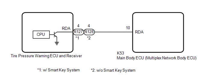
The main body ECU (multiplex network body ECU) and tire pressure warning ECU and receiver communicate by direct line. If a malfunction occurs in this communication signal, B1247 is output by the main body ECU (multiplex network body ECU).
|
DTC No. | Detection Item |
DTC Detection Condition | Trouble Area |
Note |
|---|---|---|---|---|
| B1247 |
Tire Pressure Monitor Receiver Communication Stop |
Communication between the tire pressure warning ECU and receiver and main body ECU (multiplex network body ECU) is interrupted for 10 seconds or more. |
| This DTC is for main body ECU (multiplex network body ECU) |
WIRING DIAGRAM
CAUTION / NOTICE / HINT
NOTICE:
- When replacing the tire pressure warning ECU and receiver, read the transmitter IDs and number of the transmitters (4 or 5) stored in the old ECU using the Techstream and write them down before removal.
- It is necessary to perform initialization
.gif) after registration
of the transmitter IDs into the tire pressure warning ECU and receiver after the ECU has been replaced.
after registration
of the transmitter IDs into the tire pressure warning ECU and receiver after the ECU has been replaced.
- Before replacing the main body ECU (multiplex network body ECU), refer to Registration.*
Click here
- *: w/ Smart Key System
PROCEDURE
|
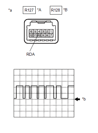
1. | INSPECT TIRE PRESSURE WARNING ECU AND RECEIVER (OUTPUT WAVEFORM) |
| (a) Using an oscilloscope, check the waveform. NOTICE: With the connector connected, check from the backside of the connector. OK: w/ Smart Key System
|
|
|
Result | Proceed to |
|---|---|
|
Waveform is as shown in the illustration. (Waveform alternates between 10.5 V or higher and 0.5 V or less) |
A |
| Waveform does not change from 10.5 V or higher |
B |
| Waveform does not change from 0.5 V or less |
C |
| A |
.gif) | REPLACE MAIN BODY ECU (MULTIPLEX NETWORK BODY ECU) |
| B |
| REPLACE TIRE PRESSURE WARNING ECU AND RECEIVER |
|
.gif)
| 2. |
CHECK TERMINAL VOLTAGE (MAIN BODY ECU (MULTIPLEX NETWORK BODY ECU) OUTPUT) |
(a) Disconnect the R127 or R128 tire pressure warning ECU and receiver connector.
(b) Measure the voltage according to the value(s) in the table below.
Standard Voltage:
w/ Smart Key System|
Tester Connection | Condition |
Specified Condition |
|---|---|---|
|
R127-4 (RDA) - Body ground |
Ignition switch ON | 10.5 V or higher |
|
Tester Connection | Condition |
Specified Condition |
|---|---|---|
|
R128-4 (RDA) - Body ground |
Ignition switch ON | 10.5 V or higher |
| OK | | REPLACE TIRE PRESSURE WARNING ECU AND RECEIVER |
|
| 3. |
CHECK HARNESS AND CONNECTOR (MAIN BODY ECU (MULTIPLEX NETWORK BODY ECU) - TIRE PRESSURE WARNING ECU AND RECEIVER) |
(a) Turn the ignition switch off.
(b) Disconnect the K53 main body ECU (multiplex network body ECU) connector.
(c) Measure the resistance according to the value(s) in the table below.
Standard Resistance:
w/ Smart Key System|
Tester Connection | Condition |
Specified Condition |
|---|---|---|
|
K53-10 (RDA) - R127-4 (RDA) |
Always | Below 1 Ω |
|
K53-10 (RDA) or R127-4 (RDA) - Body ground |
Always | 10 kΩ or higher |
|
Tester Connection | Condition |
Specified Condition |
|---|---|---|
|
K53-10 (RDA) - R128-4 (RDA) |
Always | Below 1 Ω |
|
K53-10 (RDA) or R128-4 (RDA) - Body ground |
Always | 10 kΩ or higher |
| OK | | REPLACE MAIN BODY ECU (MULTIPLEX NETWORK BODY ECU) |
| NG | | REPAIR OR REPLACE HARNESS OR CONNECTOR |
READ NEXT:
 Transmitter ID1 Operation Stop (C2111-C2115)
DESCRIPTION The tire pressure warning valve and transmitters that are installed in the tire and wheel assemblies measure the tire pressure of each wheel. The measured values are transmitted to the tir
Transmitter ID 1 not Received (Main) (C2121-C2125,C2181-C2185)
DESCRIPTION The tire pressure warning valve and transmitters that are installed in the tire and wheel assemblies measure the tire pressure of each wheel. The measured values are transmitted to the tir
Transmitter ID not Received (Main) (C2126)
DESCRIPTION If ID registration via the automatic ID registration function is canceled or the tire pressure warning ECU and receiver does not receive data from the tire pressure warning valve and trans
SEE MORE:
Torque Converter And Drive Plate
InspectionINSPECTION PROCEDURE
1. INSPECT TORQUE CONVERTER ASSEMBLY (a) Inspect the one-way clutch. Press on the splines of the stator with a finger and rotate it. Check that it rotates smoothly when turned clockwise and rotates with difficulty when turned counterclockwise.
Diffic
Slave Module Horizontal Axis Misalignment (C1AC2)
DESCRIPTION This DTC is stored when the angle of the blind spot monitor sensor LH deviates more than the allowable range from the horizontal axis.
HINT:
If a drum tester such as a speedometer tester, brake/speedometer combination tester or chassis dynamometer is used with the blind spot monito
