
Toyota Camry (XV70): Air Conditioning Compressor Magnetic Clutch Circuit
DESCRIPTION
When the engine is running, If refrigerant pressure does not decrease when the A/C switch is turned off, the following suspected areas may be the cause.
|
Symptom | Factor |
|---|---|
|
|
WIRING DIAGRAM
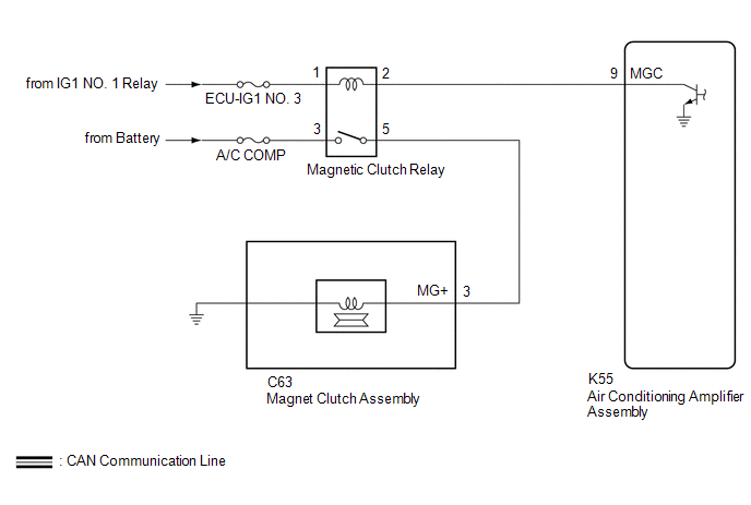
CAUTION / NOTICE / HINT
NOTICE:
Inspect the fuses for circuits related to this system before performing the following procedure.
PROCEDURE
| 1. |
INSPECT MAGNETIC CLUTCH RELAY |
(a) Remove the magnetic clutch relay.
(b) Inspect the magnetic clutch relay.
Click here
.gif)
| NG | .gif) | REPLACE MAGNETIC CLUTCH RELAY |
|
.gif)
| 2. |
CHECK HARNESS AND CONNECTOR (MAGNETIC CLUTCH RELAY - POWER SOURCE) |
(a) Measure the voltage according to the value(s) in the table below.
Standard Voltage:
|
Tester Connection | Condition |
Specified Condition |
|---|---|---|
|
Relay terminal 3 - Body ground |
Always | 11 to 14 V |
|
Relay terminal 1 - Body ground |
Ignition switch off | Below 1 V |
|
Relay terminal 1 - Body ground |
Ignition switch ON | 11 to 14 V |
| NG | | REPAIR OR REPLACE HARNESS OR CONNECTOR |
|
| 3. |
CHECK HARNESS AND CONNECTOR (MAGNETIC CLUTCH RELAY - AIR CONDITIONING AMPLIFIER ASSEMBLY) |
(a) Disconnect the K55 air conditioning amplifier assembly connector.
(b) Measure the resistance according to the value(s) in the table below.
Standard Resistance:
|
Tester Connection | Condition |
Specified Condition |
|---|---|---|
|
Relay terminal 2 - K55-9 (MGC) |
Always | Below 1 ? |
|
Relay terminal 2 or K55-9 (MGC) - Other terminals and body ground |
Always | 10 k? or higher |
| NG | | REPAIR OR REPLACE HARNESS OR CONNECTOR |
|
| 4. |
CHECK HARNESS AND CONNECTOR (MAGNETIC CLUTCH RELAY - MAGNET CLUTCH ASSEMBLY AND BODY GROUND) |
(a) Disconnect the C63 magnet clutch assembly connector.
(b) Measure the resistance according to the value(s) in the table below.
Standard Resistance:
|
Tester Connection | Condition |
Specified Condition |
|---|---|---|
|
Relay terminal 5 - C63-3 (MG+) |
Always | Below 1 ? |
|
Relay terminal 5 - C63-3 (MG+) - Other terminals and body ground |
Always | 10 k? or higher |
| NG | | REPAIR OR REPLACE HARNESS OR CONNECTOR |
|
| 5. |
CHECK HARNESS AND CONNECTOR (MAGNET CLUTCH ASSEMBLY - BODY GROUND) |
(a) Install the magnetic clutch relay.
(b) Connect the C63 magnet clutch assembly connector.
(c) Measure the voltage according to the value(s) in the table below.
Standard Voltage:
|
Tester Connection | Condition |
Specified Condition |
|---|---|---|
|
C63-3 (MG+) - Body ground |
Engine running (A/C switch: Off) |
Below 1 V |
| OK | | REPLACE MAGNET CLUTCH ASSEMBLY |
| NG | | REPAIR OR REPLACE HARNESS OR CONNECTOR |
READ NEXT:
 Ambient Temperature Display System
DESCRIPTION The thermistor assembly is installed in front of the cooler condenser assembly to detect the ambient temperature, which is used to control the automatic air conditioning system. The thermi
ECO Switch Circuit
DESCRIPTION When the ECO switch assembly (electric parking brake switch assembly) is operated, the air conditioning amplifier assembly receives a signal and enables or disables ECO mode control of the
Indicator does not Illuminate
DESCRIPTION If none of the switch indicators on the air conditioning control assembly illuminate, the following suspected areas may be the cause.
Symptom Factor
None of the switch indica
SEE MORE:
Cellular Phone Registration Failure
CAUTION / NOTICE / HINT
NOTICE:
Depending on the parts that are replaced during vehicle inspection or maintenance, performing initialization, registration or calibration may be needed. Refer to Precaution for Audio and Visual System.
Click here
When replacing the radio and display
Installation
INSTALLATION PROCEDURE 1. INSTALL ENGINE WATER PUMP ASSEMBLY
(a) Install a new water pump gasket and the engine water pump assembly with the 15 bolts.
Torque: Bolt (A) : 43 N·m {438 kgf·cm, 32 ft·lbf} Bolt (B) :
21 N·m {214 kgf·cm, 15 ft·lbf} Bolt (C) : 11 N·m {112 kgf·cm, 8
