
Toyota Camry (XV70): ECO Switch Circuit
DESCRIPTION
When the ECO switch assembly (electric parking brake switch assembly) is operated, the air conditioning amplifier assembly receives a signal and enables or disables ECO mode control of the air conditioning system.
|
Symptom | Factor |
|---|---|
|
When ECO switch assembly (electric parking brake switch assembly) is operated, blower speed does not change |
|
WIRING DIAGRAM
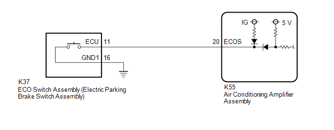
PROCEDURE
| 1. |
READ VALUE USING TECHSTREAM |
(a) Connect the Techstream to the DLC3.
(b) Turn the ignition switch to ON.
(c) Turn the Techstream on.
(d) Enter the following menus: Body Electrical / Air Conditioner / Data List.
(e) Read the Data List according to the display on the Techstream.
Body Electrical > Air Conditioner > Data List|
Tester Display | Measurement Item |
Range | Normal Condition |
Diagnostic Note |
|---|---|---|---|---|
|
ECO Switch | ECO switch assembly (electric parking brake switch assembly) |
OFF or ON | OFF: ECO switch assembly (electric parking brake switch assembly) not pushed ON: ECO switch assembly (electric parking brake switch assembly) pushed and held |
- |
|
Tester Display |
|---|
| ECO Switch |
OK:
ECO switch assembly (Electric parking brake switch assembly) condition displayed on the Techstream changes with the actual switch operation.
| OK | .gif) | REPLACE AIR CONDITIONING AMPLIFIER ASSEMBLY |
|
.gif)
| 2. |
INSPECT ECO SWITCH ASSEMBLY (ELECTRIC PARKING BRAKE SWITCH ASSEMBLY) |
(a) Remove the ECO switch assembly (electric parking brake switch assembly).
Click here .gif)
(b) Inspect the ECO switch assembly (electric parking brake switch assembly).
Click here
| NG | | REPLACE ECO SWITCH ASSEMBLY (ELECTRIC PARKING BRAKE SWITCH ASSEMBLY) |
|
| 3. |
CHECK ECO SWITCH ASSEMBLY (ELECTRIC PARKING BRAKE SWITCH ASSEMBLY) (BODY GROUND) |
(a) Measure the resistance according to the value(s) in the table below.
Standard Resistance:
|
Tester Connection | Condition |
Specified Condition |
|---|---|---|
|
K37-16 (GND1) - Body ground |
Always | Below 1 ? |
| NG | | REPAIR OR REPLACE HARNESS OR CONNECTOR |
|
| 4. |
CHECK HARNESS AND CONNECTOR (ECO SWITCH ASSEMBLY (ELECTRIC PARKING BRAKE SWITCH ASSEMBLY) - AIR CONDITIONING AMPLIFIER ASSEMBLY) |
(a) Disconnect the K55 air conditioning amplifier assembly connector.
(b) Measure the resistance according to the value(s) in the table below.
Standard Resistance:
|
Tester Connection | Condition |
Specified Condition |
|---|---|---|
|
K37-11 (ECU) - K55-20 (ECOS) |
Always | Below 1 ? |
|
K37-11 (ECU) or K55-20 (ECOS) - Other terminals and body ground |
Always | 10 k? or higher |
| OK | | REPLACE AIR CONDITIONING AMPLIFIER ASSEMBLY |
| NG | | REPAIR OR REPLACE HARNESS OR CONNECTOR |
READ NEXT:
 Indicator does not Illuminate
DESCRIPTION If none of the switch indicators on the air conditioning control assembly illuminate, the following suspected areas may be the cause.
Symptom Factor
None of the switch indica
Cooling System
DESCRIPTION If the cooling effect of the air conditioning system is weak, the following suspected areas may be the cause.
Symptom Factor
Cooling effectiveness is poor
Cooling res
Operation not Accepted Even If Air Conditioning Switch is Operated
DESCRIPTION If the air conditioning system cannot be operated using the air conditioning control assembly, the following suspected areas may be the cause.
Symptom Factor
Air conditioning
SEE MORE:
Vehicle Control History
VEHICLE CONTROL HISTORY
NOTICE:
Vehicle control history may be recorded due to the replacement or repair of related parts.
When checking the Vehicle Control History, make sure to record the output codes. Then, clear the Vehicle Control History (RoB) and check it again.
CHECK VEHICLE
Inspection
INSPECTION PROCEDURE 1. INSPECT FRONT STABILIZER LINK ASSEMBLY
(a) Inspect the turning torque of the ball joint. (1) Secure the front stabilizer link assembly in a vise using aluminum plates.
NOTICE: Do not overtighten the vise. (2) Install the nut to the front stabilizer link assembly stud
