
Toyota Camry (XV70): Cooling System
DESCRIPTION
If the cooling effect of the air conditioning system is weak, the following suspected areas may be the cause.
|
Symptom | Factor |
|---|---|
|
|
- *1: for A25A-FKS
- *2: for 2GR-FKS
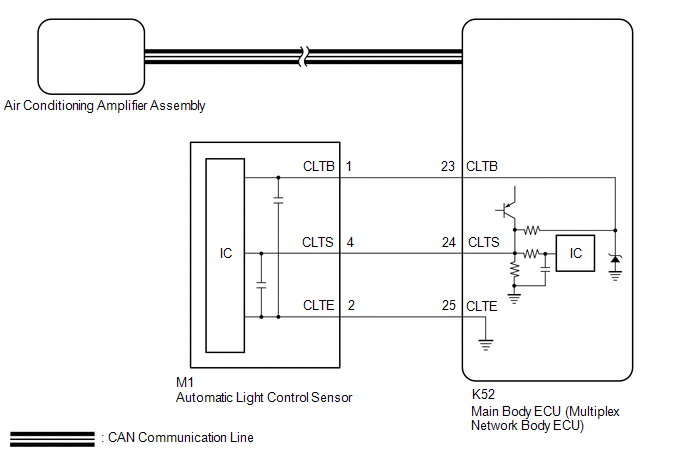
WIRING DIAGRAM
PROCEDURE
| 1. |
PERFORM REFRIGERANT SHORTAGE CHECK |
(a) Connect the Techstream to the DLC3.
(b) Turn the ignition switch to ON.
(c) Turn the Techstream on.
(d) Enter the following menus: Body Electrical / Air Conditioner / Utility / Refrigerant Gas Volume Check.
Body Electrical > Air Conditioner > Utility|
Tester Display |
|---|
| Refrigerant Gas Volume Check |
(e) Check that the following conditions are met and perform the refrigerant shortage check according to the display on the Techstream.
Measurement Condition:|
Item | Condition |
|---|---|
|
A/C switch | On |
|
Ambient temperature* |
0 to 49°C (32 to 120°F) |
|
Blower speed | HI |
*: If the ambient temperature is not within the range shown, do not perform this check.
|
Result | Amount of Refrigerant |
|---|---|
|
Refrigerant correct | Correct |
|
Refrigerant shortage |
Insufficient |
OK:
"Refrigerant correct" is displayed on Techstream.
| NG | .gif) | REPAIR REFRIGERANT LEAK |
|
.gif)
| 2. |
PERFORM ACTIVE TEST USING TECHSTREAM |
(a) Connect the Techstream to the DLC3.
(b) Turn the ignition switch to ON.
(c) Turn the Techstream on.
(d) Enter the following menus: Body Electrical / Air Conditioner / Active Test.
(e) Perform the Active Test according to the display on the Techstream.
Body Electrical > Air Conditioner > Active Test|
Tester Display | Measurement Item |
Control Range | Diagnostic Note |
|---|---|---|---|
|
Blower Motor | Blower motor with fan sub-assembly |
Min.: 0 Max.: 31 |
- |
| Air Mix Servo Targ Pulse(D) |
No. 1 air conditioning radiator damper servo sub-assembly (driver side air mix*1 or air mix*2) pulse |
Min.: 128 Max.: 383 |
Operates between 165 to 257 pulses |
|
Air Mix Servo Targ Pulse(P) |
No. 1 air conditioning radiator damper servo sub-assembly (front passenger side air mix) pulse*1 |
Min.: 128 Max.: 383 |
Operates between 255 to 347 pulses |
|
Air Outlet Servo Pulse (D) |
No. 1 air conditioning radiator damper servo sub-assembly (mode) pulse |
Min.: 128 Max.: 383 |
Operates between 241 to 348 pulses |
|
Air Inlet Damper Targ Pulse |
No. 1 blower damper servo sub-assembly pulse |
Min.: 128 Max.: 383 |
Operates between 220 to 256 pulses |
|
A/O Servo Pulse(Rr D) | No. 2 air conditioning radiator damper servo sub-assembly pulse*3 |
Min.: 128 Max.: 383 |
Operates between 158 to 260 pulses |
- *1: for Dual Type
- *2: for Single Type
- *3: w/ Rear Center Register
|
Tester Display |
|---|
| Blower Motor |
|
Tester Display |
|---|
| Air Mix Servo Targ Pulse(D) |
|
Tester Display |
|---|
| Air Mix Servo Targ Pulse(P) |
|
Tester Display |
|---|
| Air Outlet Servo Pulse (D) |
|
Tester Display |
|---|
| Air Inlet Damper Targ Pulse |
|
Tester Display |
|---|
| A/O Servo Pulse(Rr D) |
OK:
The blower motor with fan sub-assembly and each damper servo motor operates.
| NG | | GO TO DTC TROUBLESHOOTING PROCEDURE FOR MALFUNCTIONING DAMPER SERVO MOTOR |
|
| 3. |
INSPECT WIRE HARNESS AND CONNECTOR (AUTOMATIC LIGHT CONTROL SENSOR - MAIN BODY ECU (MULTIPLEX NETWORK BODY ECU)) |
(a) Disconnect the M1 automatic light control sensor connector.
(b) Disconnect the K52 main body ECU (multiplex network body ECU) connector.
(c) Measure the resistance according to the value(s) in the table below.
Standard Resistance:
|
Tester Connection | Condition |
Specified Condition |
|---|---|---|
|
M1-1 (CLTB) - K52-23 (CLTB) |
Always | Below 1 ? |
|
M1-2 (CLTE) - K52-25 (CLTE) |
Always | Below 1 ? |
|
M1-4 (CLTS) - K52-24 (CLTS) |
Always | Below 1 ? |
|
M1-1 (CLTB) or K52-23 (CLTB) - Other terminals and body ground |
Always | 10 k? or higher |
|
M1-2 (CLTE) or K52-25 (CLTE) - Other terminals and body ground |
Always | 10 k? or higher |
|
M1-4 (CLTS) or K52-24 (CLTS) - Other terminals and body ground |
Always | 10 k? or higher |
| NG | | REPAIR OR REPLACE HARNESS OR CONNECTOR |
|
| 4. |
INSPECT AUTOMATIC LIGHT CONTROL SENSOR |
(a) Remove the automatic light control sensor.
Click here
.gif)
(b) Inspect the automatic light control sensor.
Click here
| OK | | INSPECT REFRIGERANT PRESSURE WITH MANIFOLD GAUGE SET |
| NG | | REPLACE AUTOMATIC LIGHT CONTROL SENSOR |
READ NEXT:
 Operation not Accepted Even If Air Conditioning Switch is Operated
DESCRIPTION If the air conditioning system cannot be operated using the air conditioning control assembly, the following suspected areas may be the cause.
Symptom Factor
Air conditioning
Front Window Fogging
DESCRIPTION If the windshield frequently fogs up even though the air conditioning system is operating, the following suspected areas may be the cause.
Symptom Factor
Windshield frequentl
Blower Motor does not Operate
DESCRIPTION If air does not flow from the front registers after the blower switch on the air conditioning control assembly is operated, the following suspected areas may be the cause.
Symptom F
SEE MORE:
Diagnostic Trouble Code Chart
DIAGNOSTIC TROUBLE CODE CHART Air Conditioning System (for Manual Air Conditioning System)
DTC No. Detection Item
DTC Detection Condition Link
B1412 Ambient Temperature Sensor Circuit
Open or short in ambient temperature sensor circuit
B1413 Evaporator Tem
Brake Pressure Control Solenoid "A" Control Circuit Short to Battery (C13C012,...,C13C949)
DESCRIPTION The ABS solenoid relay and master cylinder cut solenoid valves are built into the brake actuator assembly.
Depending on the operating conditions, the master cylinder cut solenoid valves regulate the brake fluid pressure generated by the pump motor.
When this DTC is stored, the fail-s
