
Toyota Camry (XV70): Operation not Accepted Even If Air Conditioning Switch is Operated
DESCRIPTION
If the air conditioning system cannot be operated using the air conditioning control assembly, the following suspected areas may be the cause.
|
Symptom | Factor |
|---|---|
|
Air conditioning system cannot be operated using air conditioning control assembly
|
|
WIRING DIAGRAM
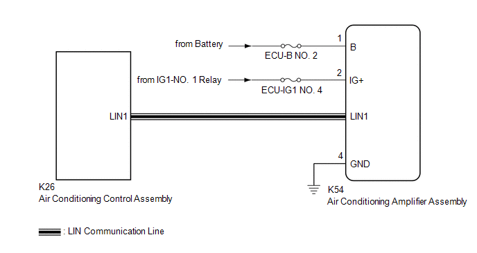
PROCEDURE
| 1. |
CHECK FOR DTC |
(a) Check for DTCs.
Body Electrical > Air Conditioner > Trouble CodesOK:
DTC B14B2 is not output.
| NG | .gif) | GO TO DTC B14B2 |
|
.gif)
| 2. |
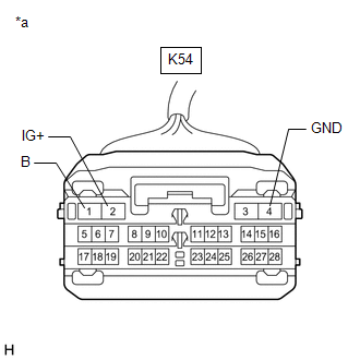
CHECK HARNESS AND CONNECTOR (AIR CONDITIONING AMPLIFIER ASSEMBLY - BATTERY AND BODY GROUND) |
|
*a | Front view of wire harness connector (to Air Conditioning Amplifier Assembly) |
(a) Disconnect the K54 air conditioning amplifier assembly connector.
(b) Measure the resistance according to the value(s) in the table below.
Standard Resistance:
|
Tester Connection | Condition |
Specified Condition |
|---|---|---|
|
K54-4 (GND) - Body ground |
Always | Below 1 ? |
(c) Measure the voltage according to the value(s) in the table below.
Standard Voltage:
|
Tester Connection | Switch Condition |
Specified Condition |
|---|---|---|
|
K54-1 (B) - Body ground |
Always | 11 to 14 V |
|
K54-2 (IG+) - Body ground |
Ignition switch ON | 11 to 14 V |
|
Ignition switch off | Below 1 V |
| OK | | REPLACE AIR CONDITIONING AMPLIFIER ASSEMBLY |
| NG | | REPAIR OR REPLACE HARNESS OR CONNECTOR |
READ NEXT:
 Front Window Fogging
DESCRIPTION If the windshield frequently fogs up even though the air conditioning system is operating, the following suspected areas may be the cause.
Symptom Factor
Windshield frequentl
Blower Motor does not Operate
DESCRIPTION If air does not flow from the front registers after the blower switch on the air conditioning control assembly is operated, the following suspected areas may be the cause.
Symptom F
Weak Blower Output
DESCRIPTION If the airflow from the front registers is weak regardless of the blower speed setting displayed on the air conditioning control assembly, the following suspected areas may be the cause.
SEE MORE:
Components
COMPONENTS ILLUSTRATION
*1 NO. 1 ENGINE UNDER COVER
*2 NO. 2 ENGINE UNDER COVER ASSEMBLY
*3 FRONT WHEEL OPENING EXTENSION PAD LH
*4 FRONT WHEEL OPENING EXTENSION PAD RH
*5 FRONT FENDER APRON SEAL LH
- -
N*m (kgf*cm, ft.*lbf): Spe
Cruise Control Input Processor (P160700)
DESCRIPTION When the ECM detects that it is not functioning normally, DTC P160700 is stored.
DTC No. Detection Item
DTC Detection Condition Trouble Area
MIL DTC Output from
P160700 Cruise Control Input Processor
When the ignition switch is ON and control of vehi
