
Toyota Camry (XV70): All Doors LOCK/UNLOCK Functions do not Operate Via Door Key Cylinder
DESCRIPTION
The main body ECU (multiplex network body ECU) receives switch signals from the door key lock and unlock switch (front door lock with motor assembly LH) and driver door key cylinder lock or unlock switch signals from the front door lock with motor assembly LH. The main body ECU (multiplex network body ECU) activates the door lock motor on each door according to these signals.
WIRING DIAGRAM
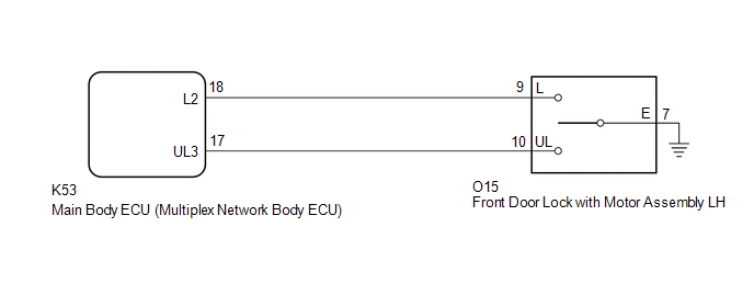
CAUTION / NOTICE / HINT
NOTICE:
Before replacing the main body ECU (multiplex network body ECU), refer to Registration.*
Click here .gif)
- *: w/ Smart Key System
PROCEDURE
|
1. | READ VALUE USING TECHSTREAM (Door Key SW-Lock, D Door Key SW-UL) |
(a) Connect the Techstream to the DLC3.
(b) Turn the ignition switch to ON.
(c) Turn the Techstream on.
(d) Enter the following menus: Body Electrical / Main Body / Data List.
(e) Read the Data List according to the display on the Techstream.
Body Electrical > Main Body > Data List|
Tester Display | Measurement Item |
Range | Normal Condition |
Diagnostic Note |
|---|---|---|---|---|
|
Door Key SW-Lock | Driver door key-linked lock / unlock switch lock signal |
OFF or ON | OFF: Driver door key cylinder not turned to lock position ON: Driver door key cylinder turned to lock position |
- |
| D Door Key SW-UL |
Driver door key-linked lock / unlock switch unlock signal |
OFF or ON | OFF: Driver door key cylinder not turned to unlock position ON: Driver door key cylinder turned to unlock position |
- |
|
Tester Display |
|---|
| Door Key SW-Lock |
|
D Door Key SW-UL |
| OK | .gif) | REPLACE MAIN BODY ECU (MULTIPLEX NETWORK BODY ECU)
|
|
.gif)
| 2. |
INSPECT FRONT DOOR LOCK WITH MOTOR ASSEMBLY LH |
(a) Remove the front door lock with motor assembly LH.
Click here
(b) Inspect the front door lock with motor assembly LH.
Click here
| NG | | REPLACE FRONT DOOR LOCK WITH MOTOR ASSEMBLY LH
|
|
| 3. |
CHECK HARNESS AND CONNECTOR (FRONT DOOR LOCK WITH MOTOR ASSEMBLY LH - MAIN BODY ECU (MULTIPLEX NETWORK BODY ECU)) |
(a) Disconnect the K53 main body ECU (multiplex network body ECU) connector.
(b) Measure the resistance according to the value(s) in the table below.
Standard Resistance:
|
Tester Connection | Condition |
Specified Condition |
|---|---|---|
|
O15-9 (L) - K53-18 (L2) |
Always | Below 1 ? |
|
O15-10 (UL) - K53-17 (UL3) |
Always | Below 1 ? |
|
O15-7 (E) - Body ground |
Always | Below 1 ? |
|
O15-9 (L) or K53-18 (L2) - Body ground |
Always | 10 k? or higher |
|
O15-10 (UL) or K53-17 (UL3) - Body ground |
Always | 10 k? or higher |
| OK | | REPLACE MAIN BODY ECU (MULTIPLEX NETWORK BODY ECU)
|
| NG | | REPAIR OR REPLACE HARNESS OR CONNECTOR |
READ NEXT:
 All Doors LOCK/UNLOCK Functions do not Operate Via Master Switch
DESCRIPTION The main body ECU (multiplex network body ECU) receives switch signals from the multiplex network master switch assembly and driver door key cylinder lock or unlock switch signals from the
All Doors LOCK/UNLOCK Functions do not Operate Via Door Control Switch
DESCRIPTION The main body ECU (multiplex network body ECU) receives switch signals from the door control switch assembly and activates the door lock motor on each door according to these signals. WIRI
Improper Operation
DESCRIPTION In cases where the doors locked or unlocked by themselves even though a door lock or unlock operation was not performed, a vehicle malfunction, accidental operation by the customer or a pa
SEE MORE:
Sensor (Motor) Failure (B2341,B2344)
DESCRIPTION When the sliding roof ECU (sliding roof drive gear sub-assembly) detects a motor malfunction and the sliding roof operation is stopped, DTC B2341 is stored.
When the sliding roof ECU (sliding roof drive gear sub-assembly) detects a gear position malfunction and the sliding roof operat
USB charging ports
The USB charging ports are used to supply 2.5 A (USB Type-A port)
or 3.0 A (USB Type-C port) of electricity at 5 V to external devices.
The USB charging ports are for charging only. They are not designed
for data transfer or other purposes.
Depending on the external device, it may not charge
