Toyota Camry (XV70): Brake Switch "A" Signal Compare Failure (P057162)
DESCRIPTION
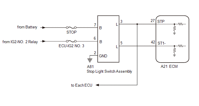
When the brake pedal is depressed, the stop light switch assembly outputs a signal to the ECM. The ECM uses this signal to control cancellation of vehicle speed by the dynamic radar cruise control. When the ECM determines that terminals STP and ST1- of the stop light switch assembly are both less than 1 V, DTC P057162 is stored.
|
DTC No. | Detection Item |
DTC Detection Condition | Trouble Area |
DTC Output from |
|---|---|---|---|---|
|
P057162 | Brake Switch "A" Signal Compare Failure |
When the ignition switch is ON and the dynamic radar cruise control system is operating, the ECM detects that the voltage at terminal STP and ST1- are both less than 1 V for approximately 0.5 seconds or more. |
| Cruise Control |
WIRING DIAGRAM
for A25A-FKS

for 2GR-FKS
CAUTION / NOTICE / HINT
NOTICE:
- Inspect the fuses for circuits related to this system before performing the following procedure.
- Before replacing the ECM, refer to Registration.
w/ Smart Key System: Click here
.gif)
w/o Smart Key System: Click here
PROCEDURE
|
1. | CHECK HARNESS AND CONNECTOR (STOP LIGHT SWITCH ASSEMBLY - BATTERY AND BODY GROUND) |
| (a) Disconnect the stop light switch assembly connector. |
|
(b) Measure the resistance according to the value(s) in the table below.
Standard Resistance:
|
Tester Connection | Condition |
Specified Condition |
|---|---|---|
|
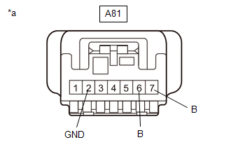
A81-2 (GND) - Body ground |
Always | Below 1 Ω |
(c) Measure the voltage according to the value(s) in the table below.
Standard Voltage:
|
Tester Connection | Condition |
Specified Condition |
|---|---|---|
|
A81-7 (B) - Body ground |
Always | 11 to 14 V |
|
A81-6 (B) - Body ground |
Ignition switch ON | 11 to 14 V |
|
Ignition switch off | Below 1 V |
| NG | .gif) | REPAIR OR REPLACE HARNESS OR CONNECTOR |
|
.gif)
| 2. |
INSPECT STOP LIGHT SWITCH ASSEMBLY |
Click here
| NG | | REPLACE STOP LIGHT SWITCH ASSEMBLY |
|
| 3. |
CHECK HARNESS AND CONNECTOR (STOP LIGHT SWITCH ASSEMBLY - ECM) |
(a) Disconnect the A81 stop light switch assembly connector.
(b) Disconnect the A24*1 or A21*2 ECM connector.
- *1: for A25A-FKS
- *2: for 2GR-FKS
(c) Disconnect each ECU connector.
(d) Measure the resistance according to the value(s) in the table below.
Standard Resistance:
for A25A-FKS:|
Tester Connection | Condition |
Specified Condition |
|---|---|---|
|
A81-3 (L) - A24-21 (STP) |
Always | Below 1 Ω |
|
A81-5 (L) - A24-22 (ST1-) |
Always | Below 1 Ω |
|
A81-3 (L) or A24-21 (STP) - Body ground |
Always | 10 kΩ or higher |
|
A81-5 (L) or A24-22 (ST1-) - Body ground |
Always | 10 kΩ or higher |
|
Tester Connection | Condition |
Specified Condition |
|---|---|---|
|
A81-3 (L) - A21-27 (STP) |
Always | Below 1 Ω |
|
A81-5 (L) - A24-42 (ST1-) |
Always | Below 1 Ω |
|
A81-3 (L) or A21-27 (STP) - Body ground |
Always | 10 kΩ or higher |
|
A81-5 (L) or A24-42 (ST1-) - Body ground |
Always | 10 kΩ or higher |
| OK | | REPLACE ECM for A25A-FKS: Click here for 2GR-FKS: Click here
|
| NG | | REPAIR OR REPLACE HARNESS OR CONNECTOR |
READ NEXT:
 Cruise Control System Internal Failure (P057504,P057549)
DESCRIPTION When the ECM detects an internal malfunction, DTC P057504 or P057549 is stored.
DTC No. Detection Item
DTC Detection Condition Trouble Area
DTC Output from
P057
Brake System (P157800)
DESCRIPTION When a malfunction in the vehicle stability control system is detected, DTC P157800 is stored.
DTC No. Detection Item
DTC Detection Condition Trouble Area
DTC Output fr
Cruise Control Input Processor (P160700)
DESCRIPTION When the ECM detects that it is not functioning normally, DTC P160700 is stored.
DTC No. Detection Item
DTC Detection Condition Trouble Area
MIL DTC Output from
SEE MORE:
Summary of functions
The head-up display is linked to the meters and navigation system (if
equipped) and projects a variety of information in front of the driver,
such as the current vehicle speed.
Driving assist system status/navigation system-linked display area
(if equipped)
The following pop-up displays
Parts Location
PARTS LOCATION ILLUSTRATION
*1 FRONT AXLE HUB SUB-ASSEMBLY RH
- FRONT SPEED SENSOR ROTOR RH
*2 FRONT SPEED SENSOR RH
*3 FRONT AXLE HUB SUB-ASSEMBLY LH
- FRONT SPEED SENSOR ROTOR LH
*4 FRONT SPEED SENSOR LH
*5 REAR AXLE HUB AND BEARING ASSEMBLY R
