Toyota Camry (XV70): Installation
INSTALLATION
CAUTION / NOTICE / HINT
HINT:
- Use the same procedure for the RH side and LH side.
- The following procedure is for the LH side.
PROCEDURE
1. INSTALL SST (for TRD)
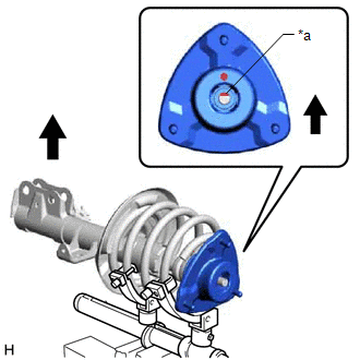
(a) Align the slot on end of the shock rod of the front shock absorber assembly as shown in the illustration.
NOTICE:
Be sure to install the part so that the slot on the front suspension support sub-assembly and the slot on the shock rod end are aligned.
|
*a | Slot |
.png) |
Outside of the Vehicle |
(b) Install SST (09727-58100) and SST (09727-58130) to the front shock absorber assembly.
SST: 09727-58100
SST: 09727-58130
SST: 09727-58010
09727-58030
|
*1 | Front Shock Absorber Assembly |
*2 | Shock Absorber Outer Shell |
|
*a | Turn |
*b | Hold |
|
*c | Fixing Nut |
*d | Bolt |
NOTICE:
Apply molybdenum grease to the bolt (area with diagonal lines) of SST (09727-58010).
.png)
.png) |
Application Area |
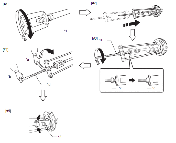
(1) Install SST (09727-58030) to the end of the shock rod of the front shock absorber assembly.[#1]
(2) Install SST (09727-58010) to the front shock absorber assembly.[#2]
NOTICE:
Take due care when installing SST (09727-58010) to ensure the shock rod is not damaged.
(3) Secure the SST (09727-58010) bolt and SST (09727-58030) with the fixing nut.[#3]
(4) After securing the SST (09727-58010) bolt, rotate the nut clockwise.[#4]
HINT:
Extend the shock rod to its maximum length to install SST (09727-58100) and SST (09727-58130).
(5) Using a piece of cloth, etc., clean the shock rod and remove any foreign matter and oil.
NOTICE:
Thoroughly clean the shock rod to prevent damage to the shock rod due to contact of foreign matter.
| (6) Clean the surface of SST (09727-58130) to which the front shock absorber assembly is installed and remove any foreign matter and oil. NOTICE: Thoroughly clean the installation surface to prevent damage to the shock rod due to contact of foreign matter. |
|
.png)
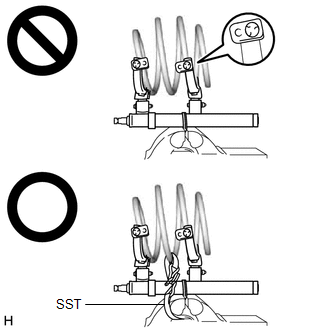
(7) Using a long ball hexagon 5, install SST (09727-58100) and SST (09727-58130) to the shock rod.[#5]
NOTICE:
Before installing, check the position of the slot on end of the shock rod.
HINT:
Install SST (09727-58100) and SST (09727-58130) to the base of the shock rod and check that SST (09727-58100) and SST (09727-58130) are securing the shock rod.
(8) After securing the SST (09727-58010) bolt, rotate the nut counterclockwise.
(9) Check that the shock rod and SST (09727-58030) have become free before releasing the fixing nut and removing SST (09727-58010) from the end of the shock rod.
NOTICE:
Take due care when removing SST (09727-58010) to ensure the shock rod is not damaged.
(10) Remove SST (09727-58030) from the end of the shock rod.
(11) Using a piece of cloth, etc., clean the end of the shock rod threads and remove any foreign matter and oil.
2. INSTALL FRONT LOWER COIL SPRING INSULATOR
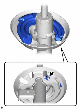
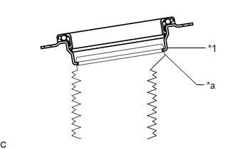
(a) Install the front lower coil spring insulator to the front shock absorber assembly.
|
|
Positioning Pin |
NOTICE:
When installing the front lower coil spring insulator, insert the positioning pin of the spring seat into the hole of the front lower coil spring insulator.
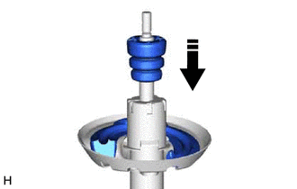
3. INSTALL FRONT SPRING BUMPER
| (a) Install the front spring bumper to the front shock absorber assembly. NOTICE:
|
|
4. INSTALL FRONT COIL SPRING
| (a) Secure SST in a vise. SST: 09727-00051 SST: 09727-30022 09727-00010 09727-00031 |
|
.png)
(b) Attach the hooks of each SST arm across the diameter of the coil spring.
CAUTION:
- Make sure that the hooks are securely attached to the coil spring.
.png)
- If a hook disengages from the coil spring, the coil spring may fly out, resulting in injury.
- Make sure that the hooks of the upper and lower SST arms are attached to the coil spring so that the distance between the hooks is as large as possible.
.png)
- If a hook disengages from the coil spring, the coil spring may fly out, resulting in injury.
- Make sure that the arms of SST are parallel and the number of coils between the arms is the same on each side.
.png)
- If a hook disengages from the coil spring, the coil spring may fly out, resulting in injury.
(c) Install the stopper pins to the hooks of SST.
CAUTION:
- Make sure that the stopper pins are installed securely.
- If a hook disengages from the coil spring, the coil spring may fly out, resulting in injury.
.png)
(d) Using SST, compress the coil spring.
CAUTION:
- If the coil spring starts to bow out while using SST, stop immediately and reattach SST correctly.
.png)
- If a hook disengages from the coil spring, the coil spring may fly out, resulting in injury.
- Do not compress the coil spring to the point where the coils touch each other.
.png)
- If a hook disengages from the coil spring, the coil spring may fly out, resulting in injury.
- Do not use an impact wrench.
.png)
- If an impact wrench is used, the threads of SST may be damaged, or sudden compression of the coil spring may cause a hook to disengage and the coil spring to fly out, resulting in injury.
- If a stopper pin touches the coil spring while using SST, remove the stopper pin and continue with the procedure.
- If a stopper pin is removed, install a coil spring stopper belt as shown in the illustration.
- If a hook disengages from the coil spring, the coil spring may fly out, resulting in injury.
SST: 09727-00110
|
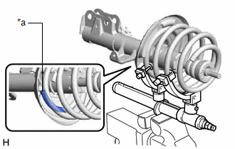
(e) Align the end of the front coil spring with the flange of the front lower coil spring insulator and install the front coil spring. NOTICE: Make sure to fit the end of the front coil spring that has the larger diameter into the depression of the front lower coil spring insulator. |
|
5. INSTALL STRUT MOUNTING BEARING
| (a) Install the strut mounting bearing to the front No. 1 shock absorber dust cover. NOTICE: Make sure that the top end of the front No. 1 shock absorber dust cover and strut mounting bearing are securely attached. |
|
6. INSTALL FRONT UPPER COIL SPRING INSULATOR
(a) Install the front upper coil spring insulator to the strut mounting bearing.
7. INSTALL STRUT MOUNTING BEARING WITH DUST COVER
(a) Install the strut mounting bearing with dust cover to the front shock absorber assembly.
8. INSTALL FRONT SUSPENSION SUPPORT SUB-ASSEMBLY
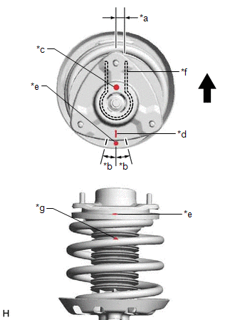
(a) Install the front suspension support sub-assembly as shown in the illustration.
|
*a | Slot |
|
|
Outside of the Vehicle |
NOTICE:
Check that the slot on the shock rod and the slot on the front suspension support sub-assembly are aligned.
(b) Align the alignment mark of the front suspension support sub-assembly with the front shock absorber lower bracket as shown in the illustration.
|
*a | 0 |
READ NEXT:
 Disposal
DISPOSAL PROCEDURE 1. DISPOSE OF FRONT SHOCK ABSORBER ASSEMBLY
CAUTION:
Always use a cloth to prevent shards of metal flying about due to the release of pressurized gas.
Always wear safety
Components
COMPONENTS ILLUSTRATION
*A for A25A-FKS
*B for 2GR-FKS
*1 FRONT NO. 1 STABILIZER BAR BUSHING
*2 FRONT NO. 1 STABILIZER BRACKET LH
*3 FRONT NO. 1 STABILI
SEE MORE:
Relay
On-vehicle InspectionON-VEHICLE INSPECTION PROCEDURE
1. INSPECT H-LP LH RELAY
(a) Measure the resistance according to the value(s) in the table below.
Standard Resistance:
Tester Connection Condition
Specified Condition
3 - 5 Voltage not applied between terminals
MIL Circuit
DESCRIPTION The Malfunction Indicator Lamp (MIL) is used to indicate vehicle malfunctions detected by the ECM.
The MIL operation can be checked visually. When the engine switch is first turned on (IG), the MIL should be illuminated and should then turn off after the engine is started. If the MIL r
