Toyota Camry (XV70): Relay
On-vehicle Inspection
ON-VEHICLE INSPECTION
PROCEDURE
1. INSPECT H-LP LH RELAY
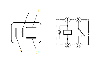
(a) Measure the resistance according to the value(s) in the table below.
Standard Resistance:
|
Tester Connection | Condition |
Specified Condition |
|---|---|---|
|
3 - 5 | Voltage not applied between terminals 1 and 2 |
10 kΩ or higher |
|
3 - 5 | Voltage applied between terminals 1 and 2 |
Below 1 Ω |
If the result is not as specified, replace the H-LP LH relay.
2. INSPECT H-LP RH RELAY
(a) Measure the resistance according to the value(s) in the table below.
Standard Resistance:
|
Tester Connection | Condition |
Specified Condition |
|---|---|---|
|
3 - 5 | Voltage not applied between terminals 1 and 2 |
10 kΩ or higher |
|
3 - 5 | Voltage applied between terminals 1 and 2 |
Below 1 Ω |
If the result is not as specified, replace the H-LP RH relay.
3. INSPECT DIM RELAY
(a) Measure the resistance according to the value(s) in the table below.
Standard Resistance:
|
Tester Connection | Condition |
Specified Condition |
|---|---|---|
|
3 - 5 | Voltage not applied between terminals 1 and 2 |
10 kΩ or higher |
|
3 - 5 | Voltage applied between terminals 1 and 2 |
Below 1 Ω |
If the result is not as specified, replace the DIM relay.
4. INSPECT DRL RELAY (for LED Type Turn Signal Light)
(a) Measure the resistance according to the value(s) in the table below.
Standard Resistance:
|
Tester Connection | Condition |
Specified Condition |
|---|---|---|
|
3 - 5 | Voltage not applied between terminals 1 and 2 |
10 kΩ or higher |
|
3 - 5 | Voltage applied between terminals 1 and 2 |
Below 1 Ω |
If the result is not as specified, replace the DRL relay.
READ NEXT:
 Components
COMPONENTS ILLUSTRATION
*A for Type A
*B w/o Panoramic View Monitor System
*C w/ Panoramic View Monitor System
- -
*1 OUTER MIRROR
*2 OU
Removal
REMOVAL CAUTION / NOTICE / HINT
The necessary procedures (adjustment, calibration, initialization, or registration) that must be performed after parts are removed and installed, or replaced during
SEE MORE:
Installation
INSTALLATION PROCEDURE 1. INSTALL TIRE PRESSURE WARNING ECU AND RECEIVER
NOTICE:
Do not drop, strike or otherwise subject the tire pressure warning ECU and receiver to impact.
If the tire pressure warning ECU and receiver is subjected to an impact, replace it with a new one.
(a) C
ABS Warning Light does not Come ON
DESCRIPTION The skid control ECU (brake actuator assembly) controls the ABS warning light in the combination meter assembly via CAN communication. CAUTION / NOTICE / HINT
NOTICE: After replacing the skid control ECU (brake actuator assembly), perform acceleration sensor zero point calibration and
