
Toyota Camry (XV70): Components
COMPONENTS
ILLUSTRATION
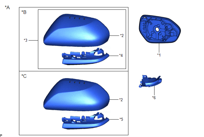
|
*A | for Type A |
*B | w/o Panoramic View Monitor System |
|
*C | w/ Panoramic View Monitor System |
- | - |
|
*1 | OUTER MIRROR |
*2 | OUTER MIRROR COVER |
|
*3 | OUTER MIRROR COVER WITH OUTER MIRROR HOLE COVER |
*4 | OUTER MIRROR HOLE COVER ASSEMBLY |
|
*5 | OUTER MIRROR HOLE COVER WITH SIDE TELEVISION CAMERA ASSEMBLY |
*6 | SIDE TURN SIGNAL LIGHT ASSEMBLY |
ILLUSTRATION
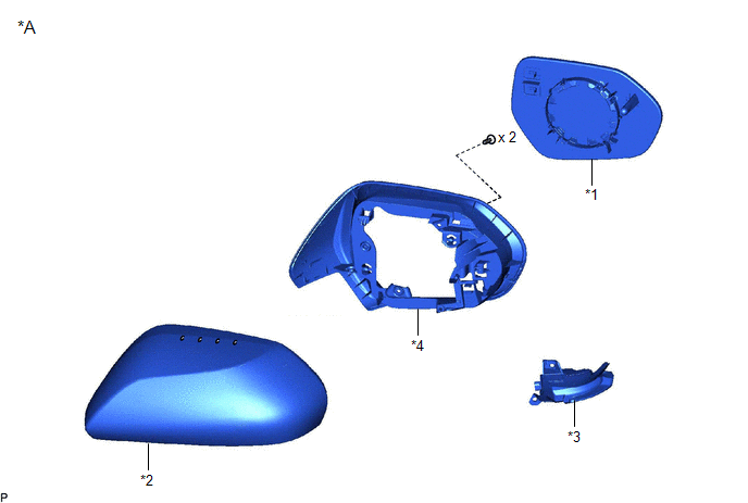
|
*A | for Type B |
- | - |
|
*1 | OUTER MIRROR |
*2 | OUTER MIRROR COVER |
|
*3 | SIDE TURN SIGNAL LIGHT ASSEMBLY |
*4 | VISOR HOUSING |
READ NEXT:
 Removal
REMOVAL CAUTION / NOTICE / HINT
The necessary procedures (adjustment, calibration, initialization, or registration) that must be performed after parts are removed and installed, or replaced during
Inspection
INSPECTION PROCEDURE 1. INSPECT SIDE TURN SIGNAL LIGHT ASSEMBLY LH
*a Component without harness connected
(Side Turn Signal Light Assembly LH)
(a) Apply battery voltage to th
Installation
INSTALLATION CAUTION / NOTICE / HINT
HINT:
Use the same procedure for the RH side and LH side.
The following procedure is for the LH side.
PROCEDURE 1. INSTALL SIDE TURN SIGNAL LIGH
SEE MORE:
Suggestion function
Displays suggestions to the driver in the following situations. To select
a response to a displayed suggestion, use the meter control switches.
The suggestion function can be turned on/off.
■ Suggestion to turn off the headlights
If the headlights are left on for a certain amount of time aft
Toyota Safety
Sense 2.5+
The Toyota Safety Sense 2.5+ consists of the following drive
assist systems and contributes to a safe and comfortable driving
experience:
Driving assist system
◆ PCS (Pre-Collision System)
◆ LTA (Lane Tracing Assist)
◆ AHB (Automatic High Beam)
◆ RSA (Road Sign Assist) (if equipped)
© 2023-2026 Copyright www.tocamry.com
