Toyota Camry (XV70): Removal
REMOVAL
CAUTION / NOTICE / HINT
The necessary procedures (adjustment, calibration, initialization, or registration) that must be performed after parts are removed and installed, or replaced during side turn signal light assembly with cover removal/installation are shown below.
Necessary Procedure After Parts Removed/Installed/Replaced|
Replaced Part or Performed Procedure |
Necessary Procedure | Effect/Inoperative Function when Necessary Procedure not Performed |
Link |
|---|---|---|---|
| *1: Applies only for when removing and installing or replacing the rear television camera assembly. | |||
| Side television camera view adjustment |
Panoramic view monitor system |
|
Replacement or removal and installation of 2 or more parts:
|
| ||
HINT:
- Use the same procedure for the RH side and LH side.
- The following procedure is for the LH side.
PROCEDURE
1. REMOVE OUTER MIRROR (for Type A)
Click here .gif)
2. REMOVE OUTER MIRROR COVER WITH OUTER MIRROR HOLE COVER (for Type A)
w/o Panoramic View Monitor System:
Click here
3. REMOVE OUTER MIRROR COVER (for Type A)
Click here
4. REMOVE OUTER MIRROR HOLE COVER WITH SIDE TELEVISION CAMERA ASSEMBLY (for Type A)
w/ Panoramic View Monitor System:
Click here
5. REMOVE OUTER MIRROR (for Type B)
Click here
6. REMOVE OUTER MIRROR COVER (for Type B)
Click here
7. REMOVE VISOR HOUSING (for Type B)
Click here
8. REMOVE SIDE TURN SIGNAL LIGHT ASSEMBLY
(a) for Type A:
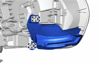
| (1) Disengage the 2 claws. |
|
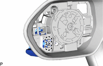
| (2) Disengage the 2 guides to separate the side turn signal light assembly. |
|
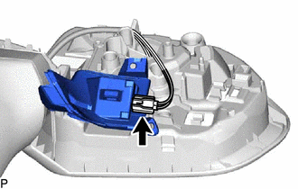
| (3) Disconnect the connector to remove the side turn signal light assembly. |
|
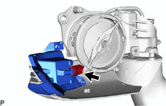
(b) for Type B:
| (1) Disconnect the connector to remove the side turn signal light assembly. |
|
READ NEXT:
 Inspection
INSPECTION PROCEDURE 1. INSPECT SIDE TURN SIGNAL LIGHT ASSEMBLY LH
*a Component without harness connected
(Side Turn Signal Light Assembly LH)
(a) Apply battery voltage to th
Installation
INSTALLATION CAUTION / NOTICE / HINT
HINT:
Use the same procedure for the RH side and LH side.
The following procedure is for the LH side.
PROCEDURE 1. INSTALL SIDE TURN SIGNAL LIGH
SEE MORE:
Installation
INSTALLATION CAUTION / NOTICE / HINT
HINT:
Use the same procedure for the RH side and LH side.
The following procedure is for the LH side.
PROCEDURE 1. INSTALL FRONT DOOR UPPER WINDOW FRAME MOULDING
(a) Engage the guide and clamp to temporarily install the front door upper wind
General Information
GENERAL INFORMATION GENERAL DESCRIPTION (a) This manual is written in accordance with SAE J2008.
(b) Repair operations can be separated mainly into the following 3 processes:
(1) Diagnosis (2) Removing/Installing, Replacing, Disassembling/Reassembling, Checking and Adjusting
(3) Final Inspecti
