
Toyota Camry (XV70): Inspection
INSPECTION
PROCEDURE
1. INSPECT SIDE TURN SIGNAL LIGHT ASSEMBLY LH
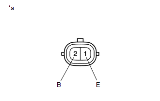
|
*a | Component without harness connected (Side Turn Signal Light Assembly LH) |
(a) Apply battery voltage to the side turn signal light assembly LH and check that the light illuminates.
OK:
|
Condition | Specified Condition |
|---|---|
|
Battery positive (+) → Terminal 2 (B) Battery negative (-) → Terminal 1 (E) |
Side turn signal light illuminates |
If the result is not as specified, replace the side turn signal light assembly LH.
2. INSPECT SIDE TURN SIGNAL LIGHT ASSEMBLY RH
|
*a | Component without harness connected (Side Turn Signal Light Assembly RH) |
(a) Apply battery voltage to the side turn signal light assembly RH and check that the light illuminates.
OK:
|
Condition | Specified Condition |
|---|---|
|
Battery positive (+) → Terminal 2 (B) Battery negative (-) → Terminal 1 (E) |
Side turn signal light illuminates |
If the result is not as specified, replace the side turn signal light assembly RH.
READ NEXT:
 Installation
INSTALLATION CAUTION / NOTICE / HINT
HINT:
Use the same procedure for the RH side and LH side.
The following procedure is for the LH side.
PROCEDURE 1. INSTALL SIDE TURN SIGNAL LIGH
Components
COMPONENTS ILLUSTRATION
*1 NO. 1 INSTRUMENT PANEL UNDER COVER SUB-ASSEMBLY
*2 STOP LIGHT SWITCH ASSEMBLY
SEE MORE:
Components
COMPONENTS ILLUSTRATION
*1 FRONT CENTER UPPER SUSPENSION BRACE SUB-ASSEMBLY
- -
Tightening torque for "Major areas involving basic vehicle performance such as moving/turning/stopping" : N*m (kgf*cm, ft.*lbf)
N*m (kgf*cm, ft.*lbf): Specified torque
Removal
REMOVAL CAUTION / NOTICE / HINT
HINT:
Use the same procedure for the RH side and LH side.
The following procedure is for the LH side.
PROCEDURE 1. REMOVE REAR WHEEL Click here
2. REMOVE REAR AXLE SHAFT NUT
(a) Using SST and a hammer, release the staked part of the rear axle s
