
Toyota Camry (XV70): Components
COMPONENTS
ILLUSTRATION
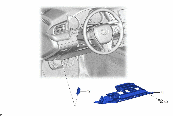
|
*1 | NO. 1 INSTRUMENT PANEL UNDER COVER SUB-ASSEMBLY |
*2 | STOP LIGHT SWITCH ASSEMBLY |
READ NEXT:
 On-vehicle Inspection
ON-VEHICLE INSPECTION PROCEDURE
1. INSPECT STOP LIGHT SWITCH ASSEMBLY (a) Disconnect the A81 stop light switch assembly connector.
(b) Measure the voltage and resistance on the wire harness
Removal
REMOVAL PROCEDURE 1. REMOVE NO. 1 INSTRUMENT PANEL UNDER COVER SUB-ASSEMBLY
Click here
2. REMOVE STOP LIGHT SWITCH ASSEMBLY
(a) Disconnect the connector.
(b) Tu
Installation
INSTALLATION PROCEDURE 1. INSTALL STOP LIGHT SWITCH ASSEMBLY
(a) Insert the stop light switch assembly until the threaded sleeve hits the pedal.
NOTICE: When inserting the stop light switch
SEE MORE:
Left Rear Wheel Speed Sensor Supply Voltage Circuit Short to Ground or Open (C14E614)
DESCRIPTION Refer to DTC C050C12 Click here
DTC No. Detection Item
DTC Detection Condition Trouble Area
C14E614 Left Rear Wheel Speed Sensor Supply Voltage Circuit Short to Ground or Open
An open or short in the speed sensor power supply circuit is detected for 0.1
Coolant
ComponentsCOMPONENTS ILLUSTRATION
*1 RADIATOR CAP SUB-ASSEMBLY
*2 RADIATOR DRAIN COCK PLUG
*3 NO. 1 ENGINE UNDER COVER
- - ReplacementREPLACEMENT CAUTION / NOTICE / HINT
CAUTION: Do not remove the radiator cap sub-assembly or radiator drain cock plug while
© 2023-2026 Copyright www.tocamry.com
