Toyota Camry (XV70): Components
COMPONENTS
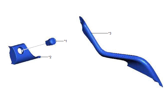
ILLUSTRATION
|
*1 | ENGINE SWITCH |
*2 | LOWER INSTRUMENT PANEL FINISH PANEL ASSEMBLY |
|
*3 | NO. 1 METER HOOD CLUSTER |
- | - |
READ NEXT:
 Removal
REMOVAL PROCEDURE 1. REMOVE NO. 1 METER HOOD CLUSTER
Click here
2. REMOVE LOWER INSTRUMENT PANEL FINISH PANEL ASSEMBLY Click here
3. REMOVE ENGINE SWITCH
(a) Disengage the 2 cla
Inspection
INSPECTION PROCEDURE 1. INSPECT ENGINE SWITCH
(a) Check the resistance.
(1) Measure the resistance according to the value(s) in the table below.
Standard Resistance:
Tester Connecti
Installation
INSTALLATION PROCEDURE 1. INSTALL ENGINE SWITCH
(a) Engage the 2 claws to install the engine switch to the lower instrument panel finish panel assembly.
2. INSTALL LOWER INSTRUMENT PANEL FINISH PA
SEE MORE:
Components
COMPONENTS ILLUSTRATION
*1 FRONT WHEEL OPENING EXTENSION PAD LH
*2 FRONT WHEEL OPENING EXTENSION PAD RH
*3 NO. 1 ENGINE UNDER COVER
- -
N*m (kgf*cm, ft.*lbf): Specified torque
- - ILLUSTRATION
*1 REAR ENGINE UNDER COVER LH
Clearance Warning ECU System Internal Failure (C161504)
DESCRIPTION This DTC is stored if the clearance warning ECU assembly self-diagnosis detects an internal malfunction in the clearance warning ECU assembly.
DTC No. Detection Item
DTC Detection Condition Trouble Area
C161504 Clearance Warning ECU System Internal Failure
© 2023-2026 Copyright www.tocamry.com
