Toyota Camry (XV70): Inspection
INSPECTION
PROCEDURE
1. INSPECT ENGINE SWITCH
(a) Check the resistance.
| (1) Measure the resistance according to the value(s) in the table below. Standard Resistance:
If the result is not as specified, replace the engine switch. |
|
(b) Check the LED illumination.
(1) Apply battery voltage between the terminals of the engine switch and check the illumination condition of the engine switch indicator light.
OK:
|
Condition | Specified Condition |
|---|---|
|
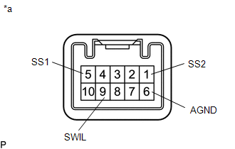
Battery positive (+) → Terminal 9 (SWIL) Battery negative (-) → Terminal 6 (AGND) |
Illuminates |
HINT:
- If the positive (+) lead and the negative (-) lead are incorrectly connected, the engine switch indicator light will not illuminate.
- If the voltage is too low, the engine switch indicator light will not illuminate.
If the result is not as specified, replace the engine switch.
READ NEXT:
 Installation
INSTALLATION PROCEDURE 1. INSTALL ENGINE SWITCH
(a) Engage the 2 claws to install the engine switch to the lower instrument panel finish panel assembly.
2. INSTALL LOWER INSTRUMENT PANEL FINISH PA
Components
COMPONENTS ILLUSTRATION
*1 ENGINE SWITCH
*2 LOWER INSTRUMENT PANEL FINISH PANEL ASSEMBLY
*3 NO. 1 METER HOOD CLUSTER
- -
Removal
REMOVAL PROCEDURE 1. REMOVE NO. 1 METER HOOD CLUSTER
Click here
2. REMOVE LOWER INSTRUMENT PANEL FINISH PANEL ASSEMBLY Click here
3. REMOVE ENGINE SWITCH
(a) Disengage the 2 cla
SEE MORE:
Pressure Control Solenoid "D" Actuator Stuck Off (P27137F)
DESCRIPTION Based on signals from the accelerator position sensor and transmission revolution sensors (NT and NC), the ECM controls the solenoid (SLT) valve using a predetermined current. As a result, the line pressure is adjusted to a pressure that is appropriate for the throttle angle and engine o
Internal Control Module Software Incompatibility Not Programmed (U030051,U030057)
DESCRIPTION
If the forward recognition camera cannot verify the vehicle information sent from the ECM, the forward recognition camera stores DTC U030051.
If the vehicle information stored in the forward recognition camera does not match the vehicle information sent from the ECM, the forwar
