Toyota Camry (XV70): Removal
REMOVAL
PROCEDURE
1. REMOVE NO. 1 METER HOOD CLUSTER
Click here .gif)
2. REMOVE LOWER INSTRUMENT PANEL FINISH PANEL ASSEMBLY
Click here
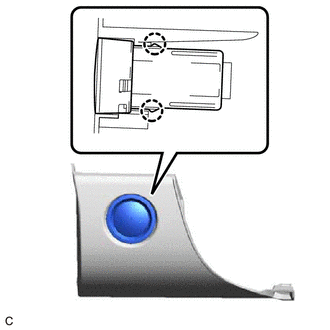
3. REMOVE ENGINE SWITCH
|
(a) Disengage the 2 claws and remove the engine switch from lower instrument panel finish panel assembly. |
|
READ NEXT:
 Inspection
INSPECTION PROCEDURE 1. INSPECT ENGINE SWITCH
(a) Check the resistance.
(1) Measure the resistance according to the value(s) in the table below.
Standard Resistance:
Tester Connecti
Installation
INSTALLATION PROCEDURE 1. INSTALL ENGINE SWITCH
(a) Engage the 2 claws to install the engine switch to the lower instrument panel finish panel assembly.
2. INSTALL LOWER INSTRUMENT PANEL FINISH PA
Components
COMPONENTS ILLUSTRATION
*1 ENGINE SWITCH
*2 LOWER INSTRUMENT PANEL FINISH PANEL ASSEMBLY
*3 NO. 1 METER HOOD CLUSTER
- -
SEE MORE:
Knock Sensor 1 Bank 1 or Single Sensor Circuit Short to Ground (P032511,P033011)
DESCRIPTION A flat-type knock control sensor (non-resonant type) has a structure that can detect vibrations between approximately 5 kHz and 15 kHz.
The knock control sensor is fitted onto the engine block to detect engine knocking.
The knock control sensor contains a piezoelectric element which
Steering Angle Sensor Supply Voltage Circuit Circuit Short to Ground or Open (C14FE14)
DESCRIPTION This DTC is stored when the skid control ECU (brake actuator assembly) receives a +B line open signal from the steering angle sensor.
DTC No. Detection Item
DTC Detection Condition Trouble Area
C14FE14 Steering Angle Sensor Supply Voltage Circuit Circuit Short to
© 2023-2026 Copyright www.tocamry.com
