Toyota Camry (XV70): Components
COMPONENTS
ILLUSTRATION
.png)
|
*1 | FRONT FENDER APRON SEAL RH |
*2 | V-BANK COVER SUB-ASSEMBLY |
.png) |
N*m (kgf*cm, ft.*lbf): Specified torque |
- | - |
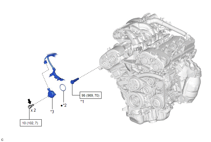
ILLUSTRATION
|
*1 | CAMSHAFT TIMING GEAR BOLT |
*2 | O-RING |
|
*3 | CAMSHAFT TIMING OIL CONTROL SOLENOID ASSEMBLY (for Intake Side of Bank 1) |
- | - |
|
|
N*m (kgf*cm, ft.*lbf): Specified torque |
● | Non-reusable part |
.png) |
Adhesive 1324 | ★ |
Precoated part |
READ NEXT:
 Removal
REMOVAL PROCEDURE 1. REMOVE FRONT WHEEL RH
Click here 2. REMOVE FRONT FENDER APRON SEAL RH
Click here
3. REMOVE V-BANK COVER SUB-ASSEMBLY Click here
4. REMOVE CAMSHAFT TI
Inspection
INSPECTION PROCEDURE 1. INSPECT CAMSHAFT TIMING GEAR BOLT
(a) Check the stroke of the plunger in the center of the camshaft timing gear bolt.
Standard Stroke: 4.5 mm (0.177 in.) or more HINT
Installation
INSTALLATION PROCEDURE 1. INSTALL CAMSHAFT TIMING GEAR BOLT
(a) Make sure that the No. 1 cylinder is at TDC/compression. HINT:
Check that the cutout of the camshaft timing gear assembly is at the
SEE MORE:
Initialization Switch Error (for Test Diagnosis) (C2198)
DESCRIPTION The switch circuit inside the combination meter assembly turns on and off according to the steering pad switch assembly operation.
During test mode, the tire pressure warning light blinks at 0.125 second intervals when "Set Pressure" is selected on the multi-information display, and il
On-vehicle Inspection
ON-VEHICLE INSPECTION PROCEDURE
1. INSPECT FUEL CUT OPERATION (a) Start the engine. (b) Warm up the engine.
(c) Increase the engine speed to approximately 3500 rpm. (d) Use a sound scope to check for fuel injector assembly operating sounds.
(e) When the accelerator pedal is fully released, che
© 2023-2026 Copyright www.tocamry.com
