Toyota Camry (XV70): Components
COMPONENTS
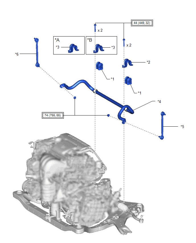
ILLUSTRATION
|
*A | for A25A-FKS |
*B | for 2GR-FKS |
|
*1 | FRONT NO. 1 STABILIZER BAR BUSHING |
*2 | FRONT NO. 1 STABILIZER BRACKET LH |
|
*3 | FRONT NO. 1 STABILIZER BRACKET RH |
*4 | FRONT STABILIZER BAR |
|
*5 | FRONT STABILIZER LINK ASSEMBLY LH |
*6 | FRONT STABILIZER LINK ASSEMBLY RH |
.png) |
Tightening torque for "Major areas involving basic vehicle performance such as moving/turning/stopping": N*m (kgf*cm, ft.*lbf) |
- | - |
READ NEXT:
 Removal
REMOVAL CAUTION / NOTICE / HINT
The necessary procedures (adjustment, calibration, initialization, or registration) that must be performed after parts are removed and installed, or replaced during f
Inspection
INSPECTION PROCEDURE 1. INSPECT FRONT STABILIZER LINK ASSEMBLY
(a) Inspect the turning torque of the ball joint. (1) Secure the front stabilizer link assembly in a vise using aluminum plates.
Installation
INSTALLATION PROCEDURE 1. INSTALL FRONT NO. 1 STABILIZER BAR BUSHING (for LH Side)
(a) Install the front No. 1 stabilizer bar bushing to the front stabilizer bar as shown in the illustration.
SEE MORE:
Dynamic radar cruise
control with full-speed
range
Summary of functions
In vehicle-to-vehicle distance control mode, the vehicle automatically
accelerates, decelerates and stops to match the speed changes of the
preceding vehicle even if the accelerator pedal is not depressed. In
constant speed control mode, the vehicle runs at a fixed speed.
Removal
REMOVAL CAUTION / NOTICE / HINT
The necessary procedures (adjustment, calibration, initialization or registration) that must be performed after parts are removed and installed, or replaced during power window regulator motor assembly removal/installation are shown below. Necessary Procedures Afte
© 2023-2026 Copyright www.tocamry.com
