Toyota Camry (XV70): Removal
REMOVAL
CAUTION / NOTICE / HINT
The necessary procedures (adjustment, calibration, initialization, or registration) that must be performed after parts are removed and installed, or replaced during front stabilizer bar removal/installation are shown below.
Necessary Procedures After Parts Removed/Installed/Replaced|
Replaced Part or Performed Procedure |
Necessary Procedure | Effect/Inoperative Function when Necessary Procedure not Performed |
Link |
|---|---|---|---|
|
*1: w/ Smart Key System
*2: w/o Smart Key System *3: When the ECM is replaced with a new one, reset memory is unnecessary. | |||
|
Battery terminal is disconnected/reconnected |
Perform steering sensor zero point calibration |
Lane Tracing Assist System |
|
|
Pre-collision system | |||
|
Memorize steering angle neutral point |
Parking Assist Monitor System |
| |
|
Panoramic view monitor system |
| ||
|
Replacement of ECM | Vehicle Identification Number (VIN) registration |
MIL comes on | for A25A-FKS:
for 2GR-FKS:
|
|
ECU communication ID registration (Immobiliser system) |
Engine start function |
w/ Smart Key System: w/o Smart Key System:
| |
| Inspection After Repair |
| for A25A-FKS:
for 2GR-FKS:
|
|
Replacement of automatic transaxle assembly |
|
| for UB80E Initialization:
for UB80E Registration:
for UA80E Initialization:
for UA80E Registration:
for UB80F Initialization:
for UB80F Registration:
|
|
Replacement of ECM (If possible, read the transaxle compensation code from the previous ECM) |
| ||
| Replacement of ECM (If impossible, read the transaxle compensation code from the previous ECM) |
| ||
| Automatic transaxle fluid |
ATF thermal degradation estimate reset |
The value of the Data List item "ATF Thermal Degradation Estimate" is not estimated correctly. |
for UB80E: for UA80E:
for UB80F:
|
|
Replacement of ECM*1 | Code registration (Smart key System (for Start Function) |
|
|
|
Replacement of ECM*2 | Code registration (Immobiliser system (w/o Smart Key System)) |
|
|
|
Front wheel alignment adjustment |
|
| w/ Electric Parking Brake System:
w/o Electric Parking Brake System:
|
|
Suspension, tires, etc. (The vehicle height changes because of suspension or tire replacement) |
Rear television camera assembly optical axis (Back camera position setting) |
Parking assist monitor system |
for Initialization: for Calibration:
|
| Panoramic view monitor system |
for Initialization: for Calibration:
| |
|
Rack and pinion power steering gear assembly |
|
|
|
PROCEDURE
1. REMOVE ENGINE ASSEMBLY WITH TRANSAXLE
for A25A-FKS: Click here
.gif)
for 2GR-FKS: Click here
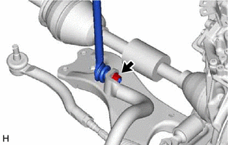
2. REMOVE FRONT STABILIZER LINK ASSEMBLY LH
| (a) Remove the nut and front stabilizer link assembly LH from the front stabilizer bar. NOTICE: Do not damage the boot of the ball joint. HINT: If the ball joint turns together with the nut, use a 6 mm hexagon socket wrench to hold the stud bolt. |
|
3. REMOVE FRONT STABILIZER LINK ASSEMBLY RH
HINT:
Perform the same procedure as for the LH side.
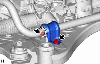
4. REMOVE FRONT NO. 1 STABILIZER BRACKET LH
| (a) Remove the 2 bolts and front No. 1 stabilizer bracket LH from the front frame assembly. |
|
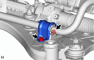
5. REMOVE FRONT NO. 1 STABILIZER BRACKET RH (for A25A-FKS)
| (a) Remove the 2 bolts and front No. 1 stabilizer bracket RH from the front frame assembly. |
|
6. REMOVE FRONT NO. 1 STABILIZER BRACKET RH (for 2GR-FKS)
HINT:
Perform the same procedure as for the LH side.
7. REMOVE FRONT STABILIZER BAR
(a) Remove the front stabilizer bar with 2 front stabilizer bar bushings from the front frame assembly.
8. REMOVE FRONT NO. 1 STABILIZER BAR BUSHING (for LH Side)
(a) Remove the front No. 1 stabilizer bar bushing from the front stabilizer bar.
9. REMOVE FRONT NO. 1 STABILIZER BAR BUSHING (for RH Side)
HINT:
Perform the same procedure as for the LH side.
READ NEXT:
 Inspection
INSPECTION PROCEDURE 1. INSPECT FRONT STABILIZER LINK ASSEMBLY
(a) Inspect the turning torque of the ball joint. (1) Secure the front stabilizer link assembly in a vise using aluminum plates.
Installation
INSTALLATION PROCEDURE 1. INSTALL FRONT NO. 1 STABILIZER BAR BUSHING (for LH Side)
(a) Install the front No. 1 stabilizer bar bushing to the front stabilizer bar as shown in the illustration.
SEE MORE:
How To Proceed With Troubleshooting
HOW TO PROCEED WITH TROUBLESHOOTING OPERATION FLOW
HINT: Perform troubleshooting in accordance with the procedure below. The following is an outline of basic troubleshooting procedure. Confirm the troubleshooting procedure for the circuit you are working on before beginning troubleshooting.
1.VE
Installation
INSTALLATION PROCEDURE 1. INSTALL TAIL EXHAUST PIPE BAFFLE SUB-ASSEMBLY
HINT:
Perform this procedure only when replacement of the tail exhaust pipe baffle sub-assembly is necessary.
If the tail exhaust pipe baffle sub-assembly is removed, replace it with a new one.
(a) Type A (w/ Tai
