Toyota Camry (XV70): Camera Heater
Components
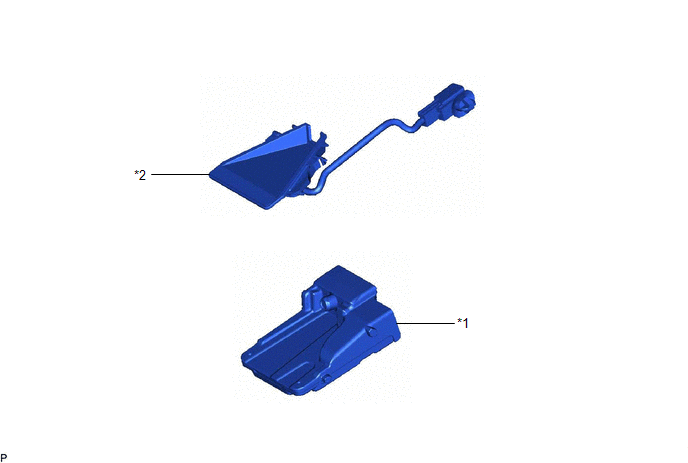
COMPONENTS
ILLUSTRATION
|
*1 | FORWARD RECOGNITION CAMERA |
*2 | FORWARD RECOGNITION WITH HEATER HOOD SUB-ASSEMBLY |
Removal
REMOVAL
PROCEDURE
1. REMOVE FORWARD RECOGNITION CAMERA
Click here
.gif)
2. REMOVE FORWARD RECOGNITION WITH HEATER HOOD SUB-ASSEMBLY
NOTICE:
- Do not touch the inner surface of the forward recognition with heater hood sub-assembly.
- Do not apply force to the heating element of the forward recognition with heater hood sub-assembly or an open circuit may result.
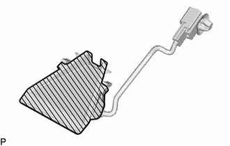
.png) |
Inner Surface of Forward Recognition with Heater Hood Sub-assembly |
| (a) Disconnect the connector. NOTICE: Do not pull the harness forcibly when disconnecting the connector. |
|
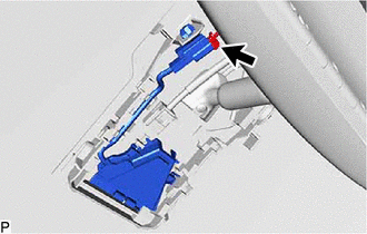
| (b) Disengage the connector clamp. |
|
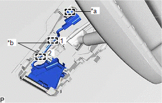
(c) Disengage the 2 wire harness clamps in the order shown in the illustration.
NOTICE:
Do not forcibly pull the wire harness as it may become damaged.
(d) Pull the forward recognition with heater hood sub-assembly in the direction indicated by the arrow (1) shown in the illustration to disengage the 2 claws.
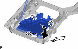
.png) |
Remove in this Direction (1) |
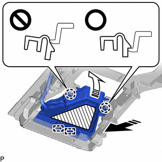
.png) |
Remove in this Direction (2) |
(e) Pull the forward recognition with heater hood sub-assembly in the direction indicated by the arrow (2) shown in the illustration to disengage the 2 guides and remove the forward recognition with heater hood sub-assembly.
Installation
INSTALLATION
PROCEDURE
1. INSTALL FORWARD RECOGNITION WITH HEATER HOOD SUB-ASSEMBLY
NOTICE:
- Do not touch the inner surface of the forward recognition with heater hood sub-assembly.
- Do not apply force to the heating element of the forward recognition with heater hood sub-assembly or an open circuit may result.

.png) |
Inner Surface of Forward Recognition with Heater Hood Sub-assembly |
(a) Engage the 2 guides and 2 claws as indicated by the arrows in the order shown in the illustration.
|
|
Heater Area |
.png) |
Install in this Direction (1) |
.png) |
Install in this Direction (2) |
NOTICE:
- Make sure that the 2 claws are engaged as shown in the illustration. Failure to do so may result in the malfunction of systems that use the forward recognition camera.
- Do not apply force to the heating element of the forward recognition with heater hood sub-assembly or an open circuit may result.
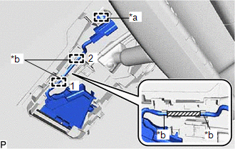
(b) With the marking tape of the wire harness in between the 2 wire harness clamps, engage the 2 wire harness clamps in the order shown in the illustration.
|
*a | Connector Clamp |
|
*b | Wire Harness Clamp |
|
|
Marking Tape |
NOTICE:
- Do not forcibly pull the wire harness as it may become damaged.
- As the No. 1 forward recognition cover cannot be installed correctly if the wire harness clamps are not engaged securely, make sure to engage the wire harness clamps securely.
(c) Engage the connector clamp to install the forward recognition with heater hood sub-assembly.
NOTICE:
As the No. 1 forward recognition cover cannot be installed correctly if the connector clamp is not engaged securely, make sure to engage the connector clamp securely.
(d) Connect the connector.
2. INSTALL FORWARD RECOGNITION CAMERA
Click here .gif)
READ NEXT:
 Precaution
PRECAUTION PRECAUTION FOR DISCONNECTING CABLE FROM NEGATIVE BATTERY TERMINAL
NOTICE: When disconnecting the cable from the negative (-) battery terminal, initialize the following systems after the c
Definition Of Terms
DEFINITION OF TERMS
Term Definition
Monitor Description Description of what the ECM monitors and how it detects malfunctions (monitoring purpose and details).
Related DTCs
SEE MORE:
Installation
INSTALLATION PROCEDURE 1. INSTALL MASS AIR FLOW METER SUB-ASSEMBLY
HINT: Perform "Inspection After Repair" after replacing the mass air flow meter sub-assembly.
Click here
(a) Install the mass air flow meter sub-assembly to the air cleaner cap sub-assembly with the 2 screws.
NOTICE:
Inspection
INSPECTION PROCEDURE 1. INSPECT FLOW SHUTTING VALVE (WATER BY-PASS HOSE ASSEMBLY)
(a) Measure the resistance according to the value(s) in the table below.
Standard Resistance:
Tester Connection Condition
Specified Condition
1 - 2 20°C (68°F)
22 to 28 ]
