Toyota Camry (XV70): Intake Air Control Valve (for Acis)
On-vehicle Inspection
ON-VEHICLE INSPECTION
PROCEDURE
1. INSPECT INTAKE AIR CONTROL VALVE (for ACIS)
(a) Remove the V-bank cover sub-assembly.
Click here .gif)
| (b) Disconnect the vacuum hose sub-assembly from the intake air control valve (for ACIS). |
|
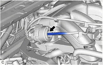
(c) Connect a hose and vacuum pump to the intake air control valve (for ACIS).
| (d) Using the vacuum pump, apply a vacuum to the intake air control valve (for ACIS). Check that the actuator rod operates when vacuum is applied. If the actuator rod does not operate when vacuum is applied, replace the intake air surge tank assembly. |
|
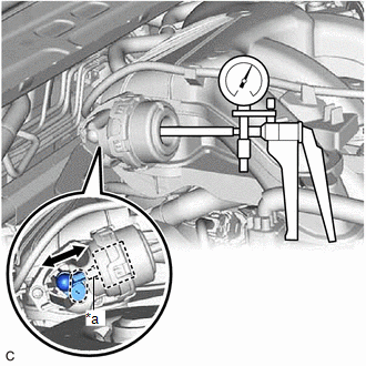
(e) Using the vacuum pump, apply a vacuum to the intake air control valve (for ACIS). Check that there is no change in vacuum after 1 minute.
If the operation is not as specified, replace the intake air surge tank assembly.
(f) Disconnect the hose and vacuum pump from the intake air control valve (for ACIS).
(g) Connect the vacuum hose sub-assembly to the intake air control valve (for ACIS).
(h) Install the V-bank cover sub-assembly.
Click here
On-vehicle Inspection
ON-VEHICLE INSPECTION
PROCEDURE
1. INSPECT INTAKE AIR CONTROL VALVE (for ACIS)
(a) Remove the V-bank cover sub-assembly.
Click here .gif)
| (b) Disconnect the vacuum hose sub-assembly from the intake air control valve (for ACIS). |
|
.png)
(c) Connect a hose and vacuum pump to the intake air control valve (for ACIS).
| (d) Using the vacuum pump, apply a vacuum to the intake air control valve (for ACIS). Check that the actuator rod operates when vacuum is applied. If the actuator rod does not operate when vacuum is applied, replace the intake air surge tank assembly. |
|
.png)
(e) Using the vacuum pump, apply a vacuum to the intake air control valve (for ACIS). Check that there is no change in vacuum after 1 minute.
If the operation is not as specified, replace the intake air surge tank assembly.
(f) Disconnect the hose and vacuum pump from the intake air control valve (for ACIS).
(g) Connect the vacuum hose sub-assembly to the intake air control valve (for ACIS).
(h) Install the V-bank cover sub-assembly.
Click here
READ NEXT:
 Components
COMPONENTS ILLUSTRATION
*1 FRONT CENTER UPPER SUSPENSION BRACE SUB-ASSEMBLY
- -
Tightening torque for "Major areas involving basic vehicle performance such as moving
Removal
REMOVAL CAUTION / NOTICE / HINT
The necessary procedures (adjustment, calibration, initialization or registration) that must be performed after parts are removed and installed, or replaced during fu
SEE MORE:
Components
COMPONENTS ILLUSTRATION
*1 FRONT FLOOR COVER LH
*2 FRONT FLOOR COVER RH
N*m (kgf*cm, ft.*lbf): Specified torque
- - ILLUSTRATION
*1 NO. 1 ENGINE UNDER COVER
*2 FRONT WHEEL OPENING EXTENSION PAD LH
*3 FRONT WHEEL OPENING EXTE
Fuel Level Sensor "A" Signal Stuck In Range (P04602A)
DESCRIPTION Refer to DTC P046012. Click here
DTC No. Detection Item
DTC Detection Condition Trouble Area
MIL Memory
Note P04602A
Fuel Level Sensor "A" Signal Stuck In Range
The change in the fuel sender gauge value is below the threshold when a certain
