Toyota Camry (XV70): Components
COMPONENTS
ILLUSTRATION
|
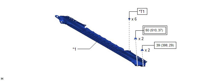
*1 | FRONT CENTER UPPER SUSPENSION BRACE SUB-ASSEMBLY |
- | - |
.png) |
Tightening torque for "Major areas involving basic vehicle performance such as moving/turning/stopping" : N*m (kgf*cm, ft.*lbf) |
.png) |
N*m (kgf*cm, ft.*lbf): Specified torque |
|
*T1 | Bolt color black: 8.0 N*m (82 kgf*cm, 71 in.*lbf) Bolt color silver: 8.9 N*m (91 kgf*cm, 79 in.*lbf) |
- | - |
ILLUSTRATION
|
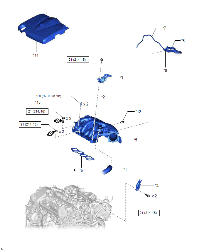
*1 | VENTILATION HOSE |
*2 | PURGE VALVE (PURGE VSV) |
|
*3 | NO. 1 FUEL VAPOR FEED HOSE |
*4 | NO. 2 SURGE TANK STAY |
|
*5 | INTAKE AIR SURGE TANK ASSEMBLY |
*6 | AIR SURGE TANK TO INTAKE MANIFOLD GASKET |
|
*7 | VACUUM HOSE SUB-ASSEMBLY |
*8 | VACUUM HOSE |
|
*9 | NO. 2 AIR TUBE |
*10 | NO. 1 V-BANK COVER BRACKET |
|
*11 | V-BANK COVER SUB-ASSEMBLY |
*12 | PLUG |
|
|
N*m (kgf*cm, ft.*lbf): Specified torque |
● | Non-reusable part |
.png) |
Do not apply lubricants (to the threaded parts) |
- | - |
ILLUSTRATION
|
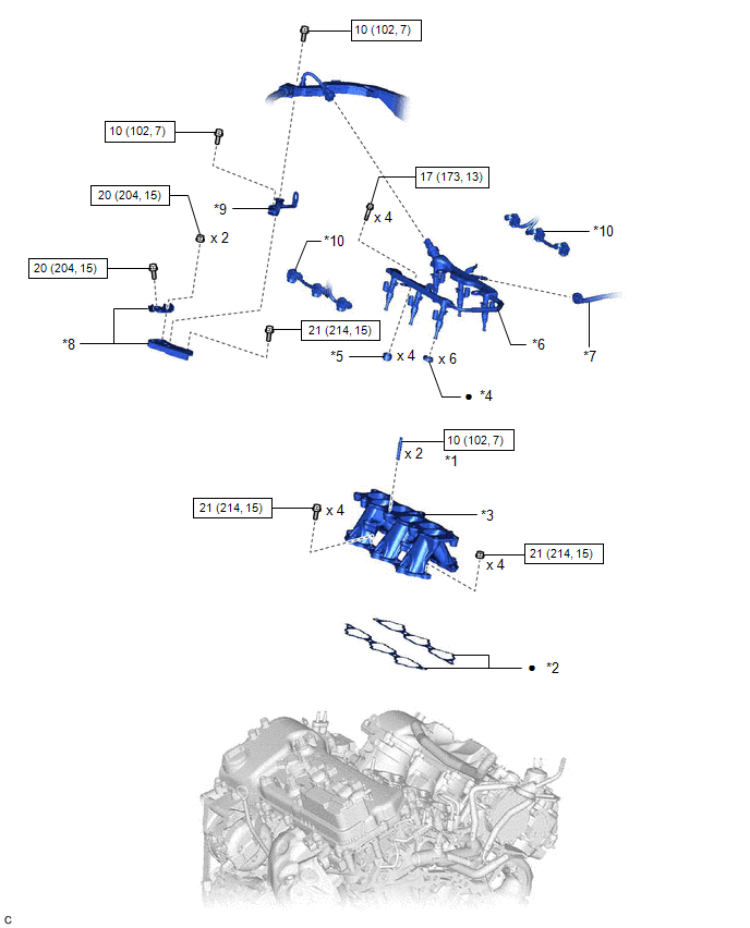
*1 | STUD BOLT |
*2 | NO. 1 INTAKE MANIFOLD TO HEAD GASKET |
|
*3 | INTAKE MANIFOLD |
*4 | INJECTOR VIBRATION INSULATOR |
|
*5 | NO. 1 DELIVERY PIPE SPACER |
*6 | FUEL DELIVERY PIPE WITH SENSOR ASSEMBLY |
|
*7 | FUEL TUBE SUB-ASSEMBLY |
*8 | NO. 2 ENGINE MOUNTING STAY RH |
|
*9 | WIRE HARNESS CLAMP BRACKET |
*10 | NO. 5 ENGINE WIRE |
|
|
N*m (kgf*cm, ft.*lbf): Specified torque |
● | Non-reusable part |
READ NEXT:
 Removal
REMOVAL CAUTION / NOTICE / HINT
The necessary procedures (adjustment, calibration, initialization or registration) that must be performed after parts are removed and installed, or replaced during fu
Installation
INSTALLATION PROCEDURE 1. INSTALL STUD BOLT
HINT: If a stud bolt is deformed or the threads are damaged, replace it.
(a) Using an E6 "TORX" socket wrench, install the 2 stud bolts to the intak
Components
COMPONENTS ILLUSTRATION
*1 FRONT CENTER UPPER SUSPENSION BRACE SUB-ASSEMBLY
- -
Tightening torque for "Major areas involving basic vehicle performance such as moving
SEE MORE:
Components
COMPONENTS ILLUSTRATION
*1 STEERING WHEEL ASSEMBLY
*2 STEERING PAD SWITCH ASSEMBLY
*3 SHIFT PADDLE SWITCH (TRANSMISSION SHIFT SWITCH ASSEMBLY)
*4 NO. 1 SWITCH WIRE
N*m (kgf*cm, ft.*lbf): Specified torque
● Non-reusable part
&
Components
COMPONENTS ILLUSTRATION
*1 FRONT FLOOR COVER LH
*2 FRONT FLOOR COVER RH
N*m (kgf*cm, ft.*lbf): Specified torque
- - ILLUSTRATION
*1 BODY MOUNTING PLATE
*2 CENTER FLOOR CROSSMEMBER BRACE
*3 FRONT CENTER FLOOR BRACE
-
